Avicenna J Dent Res. 14(2):63-68.
doi: 10.34172/ajdr.2022.12
Original Article
Effect of Anatomical Location of Dental Implants in the Mandible on Generation of Metal Artifacts on Cone-Beam Computed Tomography Scans
Azadeh Farhangnia 1  , Zoherh Reyhani 2 , Parisa Farhangnia 3 , Bahareh Hekmat 4, *
Author information:
1Assistant Professor, Department of Dental Prosthesis, School of Dentistry, Zanjan University of Medical Sciences, Zanjan, Iran
2Oral and Maxillofacial Radiologist, Private Practitioner
3Dentist, Private Practitioner
4Assistant Professor, Department of Oral and Maxillofacial Radiology, School of Dentistry, Zanjan University of Medical Sciences, Zanjan, Iran
*
Corresponding author: Bahreh Hekmat, Department of Oral and Maxillofacial Radiology, School of Dentistry, Zanjan University of Medical Sciences, Gavazng Blvd, Zanjan, Iran. Zip code: 6516647448. Tel:+98-243-3018100, Fax:+98-243-3018102, Email:
Bahar_Hekmat70@yahoo.com
Abstract
Background: Metal artifacts are the major weak points of cone-beam computed tomography (CBCT) scans. This study aimed to quantify the amount of metal artifacts generated by dental implants placed in different anatomical locations in the mandible on CBCT scans.
Methods: In this study, 98 CBCT scans of mandibular dental implants with prosthetic crowns were randomly selected irrespective of the age and gender of the patients. Of all 98 implants, 42 were placed in the anterior mandible and 56 were placed in the posterior mandible. The samples were divided into two groups of single and multiple implants. The CBCT scans of each implant were evaluated in apical and cervical cross-sections. The amount of metal artifacts generated around the implants was calculated. Data were analyzed using the Mann-Whitney U test at 0.05 level of significance.
Results: Higher amounts of artifacts were noted in the anterior mandible compared to the posterior mandible. Additionally, the amount of artifacts was higher in the cervical cross-section than in the apical cross-section. The difference in the amount of artifacts generated in the cervical cross-section was significant between single and multiple implants (P<0.05). However, this difference was not significant in the apical cross-section (P>0.05).
Conclusions: Dental implants always generate metal artifacts on CBCT scans, and the amount of generated artifacts is influenced by the anatomical location of implants in the mandibular arch.
Keywords: Anatomical, Implantation, Artifacts, Cone-Beam computed
Copyright and License Information
© 2022 The Author(s); Published by Hamadan University of Medical Sciences.
This is an open-access article distributed under the terms of the Creative Commons Attribution License (
http://creativecommons.org/licenses/by/4.0), which permits unrestricted use, distribution, and reproduction in any medium provided the original work is properly cited.
Please cite this article as follows: Farhangnia A, Reyhani Z, Farhangnia P, Hekmat B. Effect of anatomical location of dental implants in the mandible on generation of metal artifacts on cone-beam computed tomography scans. Avicenna J Dent Res. 2022; 14(2):63-68. doi:10.34172/ajdr.2022.12
Introduction
Cone-beam computed tomography (CBCT) is an imaging modality with several applications and increasing popularity in dentistry. It provides accurate 3D images, which are advantageous in many dental fields such as implantology, orthodontics, and oral and maxillofacial surgery. Most CBCT systems have the ability to generate high-resolution images that precisely visualize fine anatomical details. The numerous advantages of CBCT over conventional radiography have added to the popularity of this imaging modality for many dental applications. The main reason for the superiority of CBCT for the detection of dental lesions over 2D radiography is that it facilitates obtaining high-quality 3D images of the teeth and periodontal tissue. Moreover, the patient radiation dose in CBCT is lower than that in multi-detector computed tomography (1-3).
CBCT images are composed of voxels, which are identified by gray values, indicating the amount of absorbed X-ray beams while passing through an object. The CBCT gray value highly depends on the object properties such as density and atomic number (4,5). CBCT can provide optimal images for observation of all possible implant placement sites in edentulous patients or in those requiring multiple implants or ridge augmentation (6).
Artifacts are defined as features that appear in an image but are not present in an object. Artifacts generated by high-density materials affect the quality of CBCT images by decreasing the contrast and fading the desired structures, affecting the diagnostic quality of images. Beam hardening is the most common source of artifacts. When X-ray beams pass through an object, lower energy photons are absorbed in greater amounts than higher energy photons; this process is referred to as beam hardening. Metal artifacts are the main weak points of CBCT, which affect image quality. They are caused by metal restorations, gutta-percha, and dental implants (1).
Titanium is commonly used for the fabrication of dental implants due to its optimal physical and chemical properties and osseointegration ability. Nonetheless, titanium implants can cause artifacts (7,8). The mandible is the largest and strongest facial bone and the only mobile bone in the skull. It is composed of a body and two bony plates known as mandibular rami. Anatomical structures of the mandible include the mandibular canal, mental foramen, and anterior loop. Due to the presence of important neurovascular structures in the mandible, it should be precisely assessed radiographically prior to implant placement (9).
Artifacts can cause considerable changes in the gray value around dental implants, affecting the image quality and subsequent assessment of bone integrity and inflammatory processes around dental implants (10). This study aimed to assess the effect of anatomical location of dental implants in the mandible on the generation of metal artifacts on CBCT scans.
Materials and Methods
In this study, CBCT scans were retrieved from the archives of a private oral and maxillofacial radiology clinic. We confirm that this study was conducted in accordance with the Declaration of Helsinki. All images had been obtained by NewTom Giano CBCT scanner (Quantitative Radiology, Verona, Italy) with a 6-inch FOV, 0.25 mm voxel size, 10.65 mA, and 84 kVp. Images were examined by an oral and maxillofacial radiologist on a 20-inch monitor (LG, Seoul, Korea) in a semi-dark room. The images were divided into two groups: (I) images of dental implants placed in the anterior mandible and (II) images of dental implants placed in the posterior mandible. Additionally, the images were divided into two groups of single and multiple implants. When the distance between two adjacent implants was < 5 mm, the image would be assigned to the category of multiple implants (9).
For each implant, the axial images were reconstructed in apical and cervical cross-sections. In the cross-sectional plane of each implant, the most apical image visualizing the entire implant diameter was considered as the apical cross-section of the respective implant (Figures 1 and 2).
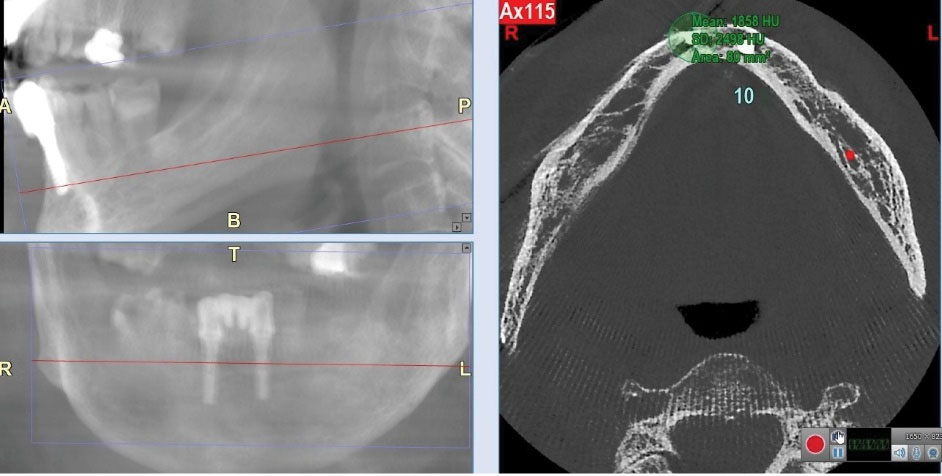
Figure 1.
Measurement of the Amount of Generated Artifacts by Determining a 10-mm ROI in the Apical Cross-section of Multiple Implants in the Anterior Mandible.
.
Measurement of the Amount of Generated Artifacts by Determining a 10-mm ROI in the Apical Cross-section of Multiple Implants in the Anterior Mandible.
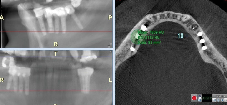
Figure 2.
Measurement of the Amount of Generated Artifacts by Determining a 10-mm ROI in the Apical Cross-section of Multiple Implants in the Posterior Mandible.
.
Measurement of the Amount of Generated Artifacts by Determining a 10-mm ROI in the Apical Cross-section of Multiple Implants in the Posterior Mandible.
The most coronal cross-sectional image before observing the prosthetic crown that visualized the entire implant diameter was considered the coronal cross-section (Figures 3 and 4).
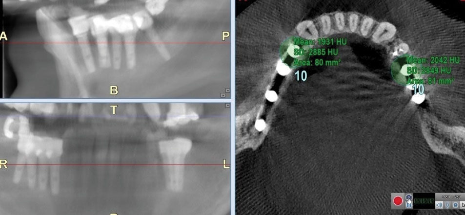
Figure 3.
Measurement of the Amount of Generated Artifacts by Determining a 10-mm ROI in the Cervical Cross-section of Multiple Implants in the Posterior Mandible.
.
Measurement of the Amount of Generated Artifacts by Determining a 10-mm ROI in the Cervical Cross-section of Multiple Implants in the Posterior Mandible.
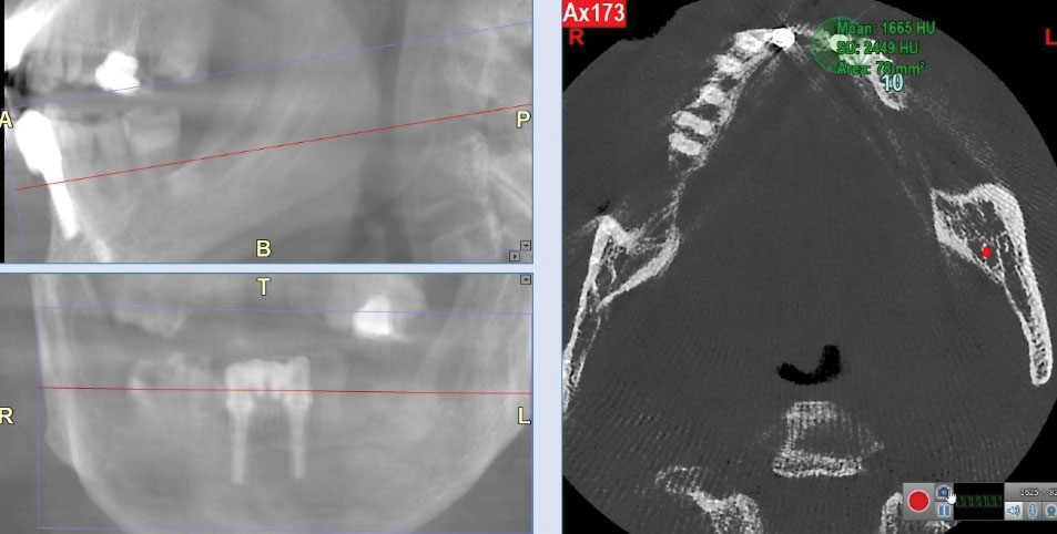
Figure 4.
Measurement of the Amount of Generated Artifacts by Determining a 10-mm ROI in the Cervical Cross-section of Multiple Implants in the Anterior Mandible.
.
Measurement of the Amount of Generated Artifacts by Determining a 10-mm ROI in the Cervical Cross-section of Multiple Implants in the Anterior Mandible.
In each of the apical and cervical cross-sections of the implants, the region of interest (ROI), which was a 10-mm diameter circle with a center coinciding with the implant center, was drawn. This region covered the entire area of the implant and the surrounding bone (10). The artifacts present in each selected ROI were counted based on the method described by Pauwels et al (5). The minimum and maximum gray values were determined using a histogram tool and these values were used for the calculation of the actual standard deviation (SD). The calculation of actual SD was performed in Excel 2020 (Windows 10, Microsoft, USA). The maximum theoretical SD is a constant value depending on the type of scanner. The images obtained by NewTom Giano CBCT scanner had a 16-bit gray scale (equal to 65 536 grey values). From this value, the maximum theoretical SD that corresponds to half the grey values of a 16-bit image was calculated (i.e., 32,768 values). According to Pauwels et al (7), artifact quantification is defined as follows: actual SD/theoretical maximum SD × 100. Therefore, the actual SD was converted into a percentage of the maximum theoretical SD, where higher percentages indicate more pronounced artifacts. Data were analyzed using Mann-Whitney U test in SPSS version 25.0 at 0.05 level of significance.
Results
Table 1 presents the distribution of dental implants in different study groups. A total of 42 implants in the anterior region and 56 implants in the posterior region were evaluated. Of implants placed in the anterior mandible, 24 were single and 18 were multiple. Of implants placed in the posterior mandible, 26 were single and 30 were multiple.
Table 1.
Distribution of Dental Implants in Different Study Groups
|
Anatomical Location
|
Single Implants
|
Multiple Implants
|
Total
|
| Anterior mandible |
24 (57%) |
18 (43%) |
42 |
| Posterior mandible |
26 (46%) |
30 (54%) |
56 |
| Total |
50 |
48 |
98 |
Table 2 shows the amount of metal artifacts generated by dental implants in the apical and cervical cross-sections on the axial plane in the anterior and posterior mandible. A significant difference was noted in the amount of generated artifacts among the study groups. The amounts of metal artifacts generated in the anterior mandible were greater compared to the posterior mandible in both cervical (P = 0.02) and apical regions (P = 0.00). Additionally, the amounts of metal artifacts generated in the cervical region of the implant were greater compared to the apical region.
Table 2.
Comparison of the Amount of Generated Metal Artifacts by Dental Implants in the Anterior and Posterior Mandible
|
Axial Plane
|
Anatomical Location of Mandible
|
Amount of Artifacts
|
P Value
|
| Apical |
Anterior |
9.46 |
0.000 |
| Posterior |
8.03 |
| Cervical |
Anterior |
10.22 |
0.024 |
| Posterior |
9.20 |
Table 3 presents the amount of generated metal artifacts by single and multiple implants in the apical and cervical cross-sections. The amount of generated metal artifacts in the apical cross-section was not significantly different between single and multiple implant groups (P = 0.35). However, the amount of generated metal artifacts in the cervical cross-section was significantly different between single and multiple implant groups, and the amount of metal artifacts was higher in the cervical cross-section of multiple implants compared with single implants (P = 0.019).
Table 3.
Comparison of the Amount of Generated Metal Artifacts in Apical and Cervical Cross-sections by Single and Multiple Dental Implants Placed in the Mandible
|
Axial plane
|
Implants
|
Amount of Artifacts
|
P
Value
|
| Apical |
Single |
8.30 |
0.358 |
| Multiple |
8.42 |
| Cervical |
Single |
9.16 |
0.019 |
| Multiple |
9.84 |
Discussion
All dental treatments are performed aiming to provide optimal function and esthetics in the dentition. Implant treatment can also help achieve these goals (11).
CBCT is an efficient imaging modality for the detection of hard and soft tissue lesions in the head and neck region, which has become an important diagnostic tool in dentistry in the past years due to low cost, high speed of image acquisition, and low patient radiation dose compared with computed tomography (8). CBCT images are widely used for diagnosis and treatment planning in patients requiring dental implants since they provide accurate 3D information (12).
Anatomical structures such as the mandibular canal, mental foramen, and the roots of adjacent teeth can be easily visualized on CBCT scans. In addition, CBCT enables precise measurement of distances, areas, and volumes. Therefore, clinicians can benefit from reliable treatment planning for patients requiring ridge augmentation, tooth extraction, and implant placement (13).
CBCT images obtained after implant placement can show metal artifacts due to the presence of previously placed implants. These artifacts can decrease the efficacy of CBCT in the postoperative phase (10).
Titanium is the main constituent of dental implants, which can generate artifacts on CBCT scans in different anatomical regions of the mandible. Nonetheless, the amount of generated artifact may vary depending on the implant position in different anatomical locations. Anatomical structures adjacent to the implant site are among the factors affecting artifact generation (10). Anatomical structures of the mandible such as the mandibular canal and mental foramen should be precisely assessed prior to implant placement since they contain important neurovascular structures. The thickness and density of the anterior and posterior mandible are also different due to the presence of different anatomical structures and can affect artifact generation (9).
In the present study, the results showed that the amount of artifacts in the anterior mandible (incisor and canine regions) was greater than that in the posterior region. This significant difference in gray value in different areas of the mandible is due to the adjacent anatomical structures and variable density and thickness of the anterior and posterior mandible.
The position of objects in the field of view changes the gray value of CBCT images. In some certain positions, the X-ray beam passes through the axis of the mandible and interferes with dental implants, teeth, and adjacent bone in a specific plane. Another possible explanation for the difference in artifacts in different anatomical locations is the effect of exomass (the entire craniofacial region inside and outside of the field of view). A great portion of the X-ray beam is absorbed by the hard tissue, affecting the quality of CBCT images; however, it is not visible on the final image. The presence of adjacent anatomical structures such as the skull and vertebral column can also affect the gray value (5,14-16).
The results of the present study were in agreement with those of a study by Machodo et al. They reported that the generated metal artifacts were influenced by the anatomical region, and the amount of generated metal artifacts was greater in the anterior mandible compared with the posterior region. In general, they showed higher amounts of artifacts compared with our study, which may be due to the type of CBCT scanner used in their study. They did not mention the type of CBCT scanner in their study; however, according to the type of software they used, which was Radiant DICOM, their CBCT scanner was probably different from that used in our study (10). In the present study, NewTom Giano CBCT scanner and NNT software were used to measure the amount of generated artifacts. According to a study by Esmaeili et al, this CBCT scanner yields images with higher quality and lower amount of metal artifacts compared with other scanners (8). Our results were in line with those of Oliveira et al, who assessed the effect of anatomical location on gray value of CBCT images. They reported higher amounts of artifacts in the anterior mandible compared with the posterior region (15). This finding was also in agreement with the results found by Queiroz et al, who assessed the efficacy of metal artifact reduction algorithm when a metal object had different positions in the field of view. They found a significant difference in image noise in different positions; in other words, less noise was detected when the object was in the central position (17). According to a study by Valizadeh et al, the position of the object in the field of view affects the gray value of CBCT images, which was in accordance with our findings (18).
In the present study, as shown in Table 3, greater artifacts were noted in the cervical cross-section of implants compared with the apical cross-section. This difference may be attributed to the presence of prosthetic restoration attached to the implant. The metal alloy used for the fabrication of prosthetic crowns has a higher atomic number than titanium, which is the main constituent of dental implants. The higher the atomic number of prosthetic crown alloy, the greater the generated metal artifacts would be. Therefore, the presence of prosthetic restorations can increase the amount of artifacts in the cervical third of dental implants. Similarly, other studies reported higher amounts of artifacts in the cervical cross-section of implants placed in the mandible compared with the apical cross-section (10,19).
The present study found no significant difference in the amount of generated artifacts between single and multiple implants in their apical cross-section. This finding may be due to the small diameter of ROI, with a standard value of 10 × 10 mm, defined for quantification of the amount of artifacts in the present study. This can result in an insignificant effect of adjacent implants on artifacts in the apical cross-section. This result was in line with the findings of a study by Machodo et al (10).
The present study revealed a significant difference in the amount of artifacts in the cervical cross-section between single and multiple implants placed in the mandible. Multiple implants showed higher amounts of artifacts in the cervical cross-section. This result was in contrast to the findings of the study by Machodo et al (10), which can be due to the fact that most implants have a divergent position relative to each other in the apical region compared with the cervical region. In other words, the inter-implant distance in the cervical region is often smaller than that in the apical region. Resultantly, the ROI of the cervical part of multiple implants is superimposed, leading to the formation of greater amounts of artifacts in the cervical region of multiple implants. Moreover, the presence of metal crowns and alveolar bone crest can further increase the amount of artifacts in the cervical cross-section of multiple implants. It is noteworthy that other factors such as the voxel size, slice thickness, and size of the field of view can affect the amount of generated artifacts. Therefore, further in vitro studies are required to address the effect of these variables when measuring the amount of artifacts generated by dental implants.
Conclusions
Considering the results of the present study and those of previous investigations, CBCT images often have metal artifacts. The anatomical location of the implant affects the amount of generated artifacts; in other words, greater artifacts are generated in the anterior mandible and cervical cross-section of dental implants.
Authors’ Contribution
AF: Conceived and designed the analysis, ZR: Conceived and designed the analysis, PF: Collected the data, Performed the analysis, Wrote the paper, BH: Conceived and designed the analysis, Wrote the paper
Ethical Statement
This study was approved by the Ethics Committee of Zanjan University of Medical Sciences (ethical approval code: IR.ZUMS.REC.1398.310).
Conflict of Interest Disclosures
The authors declare that they have no conflict of interests.
References
- Saati S, Eskandarloo A, Falahi A, Tapak L, Hekmat B. Evaluation of the efficacy of the metal artifact reduction algorithm in the detection of a vertical root fracture in endodontically treated teeth in cone-beam computed tomography images: an in vitro study. Dent Med Probl 2019; 56(4):357-63. doi: 10.17219/dmp/109902 [Crossref] [ Google Scholar]
- Shokri A, Faradmal MJ, Hekmat B. Correlations between anatomical variations of the nasal cavity and ethmoidal sinuses on cone-beam computed tomography scans. Imaging Sci Dent 2019; 49(2):103-13. doi: 10.5624/isd.2019.49.2.103 [Crossref] [ Google Scholar]
- Saati S, Foroozandeh M, Alafchi B. Radiographic characteristics of soft tissue calcification on digital panoramic images. Pesqui Bras Odontopediatria Clin Integr 2020; 20:e5053. doi: 10.1590/pboci.2020.068 [Crossref] [ Google Scholar]
- Sheikhi M, Behfarnia P, Mostajabi M, Nasri N. The efficacy of metal artifact reduction (MAR) algorithm in cone-beam computed tomography on the diagnostic accuracy of fenestration and dehiscence around dental implants. J Periodontol 2020; 91(2):209-14. doi: 10.1002/jper.18-0433 [Crossref] [ Google Scholar]
- Pauwels R, Stamatakis H, Bosmans H, Bogaerts R, Jacobs R, Horner K. Quantification of metal artifacts on cone beam computed tomography images. Clin Oral Implants Res 2013; 24 Suppl A100:94-9. doi: 10.1111/j.1600-0501.2011.02382.x [Crossref] [ Google Scholar]
- White SC, Pharoah MJ. Oral Radiology-E-Book: Principles and Interpretation. 8th ed. Elsevier Health Sciences; 2019. p. 106-8.
- Sancho-Puchades M, Hämmerle CH, Benic GI. In vitro assessment of artifacts induced by titanium, titanium-zirconium and zirconium dioxide implants in cone-beam computed tomography. Clin Oral Implants Res 2015; 26(10):1222-8. doi: 10.1111/clr.12438 [Crossref] [ Google Scholar]
- Esmaeili F, Johari M, Haddadi P, Vatankhah M. Beam hardening artifacts: comparison between two cone beam computed tomography scanners. J Dent Res Dent Clin Dent Prospects 2012; 6(2):49-53. doi: 10.5681/joddd.2012.011 [Crossref] [ Google Scholar]
- Pittayapat P, Jacobs R, Bornstein MM, Odri GA, Kwon MS, Lambrichts I. A new mandible-specific landmark reference system for three-dimensional cephalometry using cone-beam computed tomography. Eur J Orthod 2016; 38(6):563-8. doi: 10.1093/ejo/cjv088 [Crossref] [ Google Scholar]
- Machado AH, Fardim KAC, de Souza CF, Sotto-Maior BS, Assis N, Devito KL. Effect of anatomical region on the formation of metal artefacts produced by dental implants in cone beam computed tomographic images. Dentomaxillofac Radiol 2018; 47(3):20170281. doi: 10.1259/dmfr.20170281 [Crossref] [ Google Scholar]
- Seifi M, Nodehi D, Ghahramanloo A, Ahmadi Z, Farhangnia A, Saedi M. Comparing the electromyographic features of the masseter and temporal muscles in patients with full mouth implant-supported FDPs and natural dentition. Acta Inform Med 2017; 25(1):49-53. doi: 10.5455/aim.2017.25.49-53 [Crossref] [ Google Scholar]
- Vasconcelos TV, Bechara BB, McMahan CA, Freitas DQ, Noujeim M. Evaluation of artifacts generated by zirconium implants in cone-beam computed tomography images. Oral Surg Oral Med Oral Pathol Oral Radiol 2017; 123(2):265-72. doi: 10.1016/j.oooo.2016.10.021 [Crossref] [ Google Scholar]
- Misch CE. Contemporary Implant Dentistry-E-Book. St Loius: Elsevier Health Sciences; 2007.
- Benic GI, Sancho-Puchades M, Jung RE, Deyhle H, Hämmerle CH. In vitro assessment of artifacts induced by titanium dental implants in cone beam computed tomography. Clin Oral Implants Res 2013; 24(4):378-83. doi: 10.1111/clr.12048 [Crossref] [ Google Scholar]
- Oliveira ML, Tosoni GM, Lindsey DH, Mendoza K, Tetradis S, Mallya SM. Influence of anatomical location on CT numbers in cone beam computed tomography. Oral Surg Oral Med Oral Pathol Oral Radiol 2013; 115(4):558-64. doi: 10.1016/j.oooo.2013.01.021 [Crossref] [ Google Scholar]
- Schulze RK, Berndt D, d’Hoedt B. On cone-beam computed tomography artifacts induced by titanium implants. Clin Oral Implants Res 2010; 21(1):100-7. doi: 10.1111/j.1600-0501.2009.01817.x [Crossref] [ Google Scholar]
- Queiroz PM, Santaella GM, da Paz TD, Freitas DQ. Evaluation of a metal artefact reduction tool on different positions of a metal object in the FOV. Dentomaxillofac Radiol 2017; 46(3):20160366. doi: 10.1259/dmfr.20160366 [Crossref] [ Google Scholar]
- Valizadeh S, Vasegh Z, Rezapanah S, Safi Y, Khaeazifard MJ. Effect of object position in cone beam computed tomography field of view for detection of root fractures in teeth with intra-canal posts. Iran J Radiol 2015; 12(4):e25272. doi: 10.5812/iranjradiol.25272 [Crossref] [ Google Scholar]
- Naitoh M, Saburi K, Gotoh K, Kurita K, Ariji E. Metal artifacts from posterior mandibular implants as seen in CBCT. Implant Dent 2013; 22(2):151-4. doi: 10.1097/ID.0b013e318284aee2 [Crossref] [ Google Scholar]