Avicenna J Dent Res. 16(4):189-196.
doi: 10.34172/ajdr.1877
Original Article
Visibility of Inferior Alveolar Canal Borders Using Panoramic Radiography and Cross-sectional CBCT Images
Daryoush Goodarzipour 1  , Farzaneh Mosavat 1 , Mohammad Saleh Fahimzad 2, Mahsa Bayati 1, *
Author information:
1Department of Oral & Maxillofacial Radiology, Faculty of Dentistry, Tehran University of Medical Sciences, Tehran, Iran
2Private Dentist, Tehran, Iran
Abstract
Background: Clinical identification of the inferior alveolar canal (IAC) is crucial before performing surgical interventions such as mandibular third molar extraction or jaw fixation to preserve the integrity of the IAC. This study evaluated the visibility of IAC borders using panoramic radiography (conventional and CBCT reformatted) and cross-sectional CBCT images.
Methods: The conventional panoramic (CP) and CBCT images of 328 patients were evaluated, and the visibility of the IAC was assessed by three examiners across four equal 1 cm-wide regions, from anterior to posterior (Areas 1 to 4). For CBCT, reformatted panoramic (CRP) views were generated using curved multiplanar reformatting at the mandibular mid-root level within the software. Four cross-sectional images were obtained for each region. Visibility was rated as visible (score=1) or non-visible (score=0) across the three imaging modalities. Statistical significance was set at P value<0.05.
Results: Across all three radiographic modalities, the inferior border of the IAC was more consistently visible than the superior border. The highest visibility of the inferior border was observed in Area 4, with visibility rates of 92.1% for cross-sectional CBCT, 91.5% for CBCT-reformatted panoramic, and 92.4% for CP. The lowest visibility was found at the superior border in Area 2, with visibility rates of 86.9% for cross-sectional CBCT, 80.2% for CBCT-reformatted panoramic, and 67.4% for CP.
Conclusion: Visualization of the IAC in the distal area of the mental foramen is more challenging than in other areas across all radiographic modalities. Given the superior visibility levels observed in CBCT images, especially for the superior border in Areas 1, 2, and 3, CBCT is recommended over CP radiography.
Keywords: Inferior alveolar canal, Panoramic, Cone beam CT, Visibility, Mandible
Copyright and License Information
© 2024 The Author(s); Published by Hamadan University of Medical Sciences.
This is an open-access article distributed under the terms of the Creative Commons Attribution License (
https://creativecommons.org/licenses/by/4.0), which permits unrestricted use, distribution, and reproduction in any medium provided the original work is properly cited.
Please cite this article as follows: Goodarzipour D, Mosavat F, Fahimzad MS, Bayati M. Visibility of inferior alveolar canal borders using panoramic radiography and cross-sectional CBCT images. Avicenna J Dent Res. 2024; 16(4):189-196. doi:10.34172/ajdr.1877
Background
The inferior alveolar canal (IAC) is a crucial anatomical structure within the mandible, playing a pivotal role in housing the inferior alveolar nerve (IAN), artery, and vein. Accurate visualization of IAC is crucial for a range of dental and surgical procedures, as it descends obliquely from the mandibular ramus and extends horizontally along the mandibular body (1,2). On radiographic images, the IAC appears as a radiolucent zone bordered by thin radiopaque lines representing its superior and inferior borders (1,3-5). Factors such as the degree of cortication (3), surrounding trabecular bone, and the imaging modality used can significantly influence the visibility of these borders (5). The radiographic appearance of the IAC can vary considerably due to differences in imaging technique and anatomical characteristics, which can affect diagnostic accuracy (6).
The IAN plays a key role in providing essential sensory innervation to the lower lip, central teeth, gingiva, and mandible, underscoring the importance of precise IAC localization during dental and surgical procedures. Accurate identification of the IAC is crucial to avoid nerve injury, which can result in complications such as dysesthesia, paresthesia, or anesthesia (6-11). Preventing IAN damage during surgery is paramount to ensure successful outcomes and minimize postoperative complications (11,12).
Various imaging modalities are used to visualize the IAC, including panoramic radiography (3,10,13), computed tomography (CT) (10,14), and cone-beam computed tomography (CBCT) (15,16), each with distinct advantages and limitations. CT and CBCT offer three-dimensional (3D) visualization without distortions and superimposition (17). CT provides high-resolution cross-sectional images for detailed assessment of the IAC, but its high radiation exposure, high cost, and limited availability make it less ideal for routine dental use (7). Although CT offers excellent detail and accuracy, its associated radiation exposure and expense limit its routine use compared to other modalities (18,19). CBCT has emerged as a preferred imaging technique in dental practice, offering high-resolution 3D images with reduced radiation doses and costs compared to CT. It is also suitable for preoperative examinations and treatment planning due to its advantages in image quality, geometric accuracy, and cost-effectiveness (3,17,19). However, CBCT effectiveness can be influenced by factors such as voxel size and patient-specific anatomical variations, which may affect IAC visibility (20). Furthermore, the quality of CBCT images may vary depending on the used machine and settings, potentially impacting diagnostic accuracy (21).
Panoramic imaging, also known as pantomography, provides a broad overview of the mandible and maxilla, capturing both dental arches and supporting structures in a single image. It is beneficial for initial evaluations and patients incapable of tolerating intraoral imaging (8). Panoramic imaging is relatively quick and less expensive than CBCT and CT, making it a common choice for preliminary assessments (22). However, panoramic radiographs are prone to distortions and overlapping structures, which can compromise visualization (23). They may also lack the detailed cross-sectional views provided by CBCT, limiting their effectiveness in accurately assessing the canal’s anatomy and its relationship with surrounding structures. Hence, panoramic imaging can be less reliable for detailed evaluations compared to CBCT (21).
This study aimed to address a significant gap in the literature by conducting a comprehensive comparison of the visibility of the IAC using three distinct radiographic techniques: conventional panoramic (CP) radiography, cross-sectional CBCT, and CBCT-reconstructed panoramic images. Previous research has demonstrated that while CBCT provides detailed three-dimensional views of the IAC, its effectiveness can vary depending on factors such as voxel size and patient anatomy (24). Studies comparing panoramic radiography with CBCT have highlighted that CBCT generally offers superior visualization but may not always be directly comparable to traditional panoramic methods due to differences in image quality and diagnostic accuracy (24). Additionally, the use of CBCT-reconstructed panoramic images, which utilize CBCT data to generate panoramic views, remains relatively underexplored in the literature, particularly in terms of its comparative efficacy (21). Therefore, a comprehensive comparison of these three techniques is essential to identify the most effective diagnostic technique for visualizing the IAC.
The novelty of the current study lies in its unique approach, where all three modalities were evaluated within the same patient cohort. This approach provides a direct comparison of their effectiveness in visualizing the IAC, which is both intriguing and engaging. By assessing the visibility of the IAC using CP radiography, cross-sectional CBCT, and CBCT-reconstructed panoramic images, this study aimed to identify the most effective diagnostic technique. This comprehensive evaluation not only addresses existing discrepancies and limitations in previous studies but also seeks to enhance diagnostic practices and improve clinical outcomes. Insights gained from this study can enhance preoperative planning and reduce the risk of postoperative complications, thereby advancing patient care in dental and surgical practices.
Materials and Methods
Study Design
This comparative, retrospective, and cross-sectional study was conducted using radiographic records retrieved from the Tehran University of Medical Sciences, School of Dentistry database. The study protocol was approved by the institutional review board (IR.TUMS.DENTISTRY.REC.1396.2283).
Inclusion and Exclusion Criteria
Radiographs were selected based on the following inclusion criteria: dentulous patients of both genders, aged over 18 years, with diagnostic-quality panoramic and CBCT volumes taken within a maximum period of 6 months. Exclusion criteria included radiographs of insufficient quality due to distortion or technical errors, as well as patients with a history of jaw pathology, fractures, previous surgeries, or systemic rarefaction diseases such as osteoporosis, hyperparathyroidism or other conditions that lead to decreased bone density and structural weakening.
The study included 328 patients who met the criteria of having both CBCT and panoramic radiographs. A qualified radiologist conducted the initial screening, identifying patients with both types of radiographic images who met the inclusion criteria, thereby ensuring that the patient cohort had the required data for a comprehensive comparison. Subsequently, a random selection process was applied to this pre-defined pool of eligible patients to minimize potential selection biases and ensure a representative sample. Finally, this process resulted in the selection of 984 images (328 images for each radiographic technique) from the cohort of 328 patients.
Radiographic Acquisition and Analysis
Panoramic images were captured using the Planmeca ProMax X-ray system, with exposure parameters set at 80 kV, 12 mA, and 16 seconds. CBCT volumes were acquired using the Planmeca ProMax 3D X-ray unit, with exposure parameters set at 84 kV, 12 mA, and 17 seconds. In the panoramic radiographs, the mandible was divided into four equally sized areas (1 cm in width each) using five parallel lines extending from 1 centimeter anterior to the mental foramen to the posterior region (Areas 1, 2, 3, and 4), as illustrated in Figures 1 and 2. The CBCT reformatted panoramic (CRP) views were generated through a multiplanar reformatting at the mandibular mid-root level within the software. The CRP layer thickness was set to 5 mm using a sharpness filter of “2x”. Four cross-sectional images were obtained for each region, with slice thicknesses of 0.5 mm and intervals of 10 mm (Figure 3).
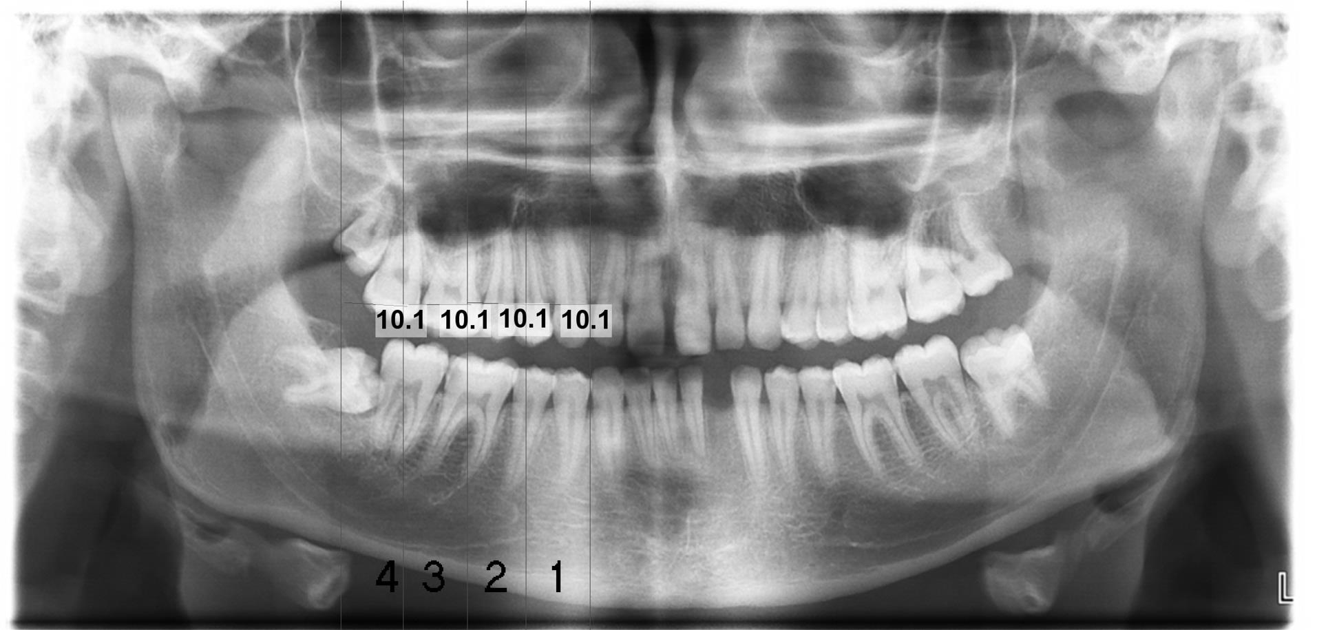
Figure 1.
A Panoramic Image. Note. The parallel lines separate the mandibular canal into 4 areas of equal width: Area 1 (1), Area 2 (2), Area 3 (3), and Area 4 (4), from anterior to posterior
.
A Panoramic Image. Note. The parallel lines separate the mandibular canal into 4 areas of equal width: Area 1 (1), Area 2 (2), Area 3 (3), and Area 4 (4), from anterior to posterior
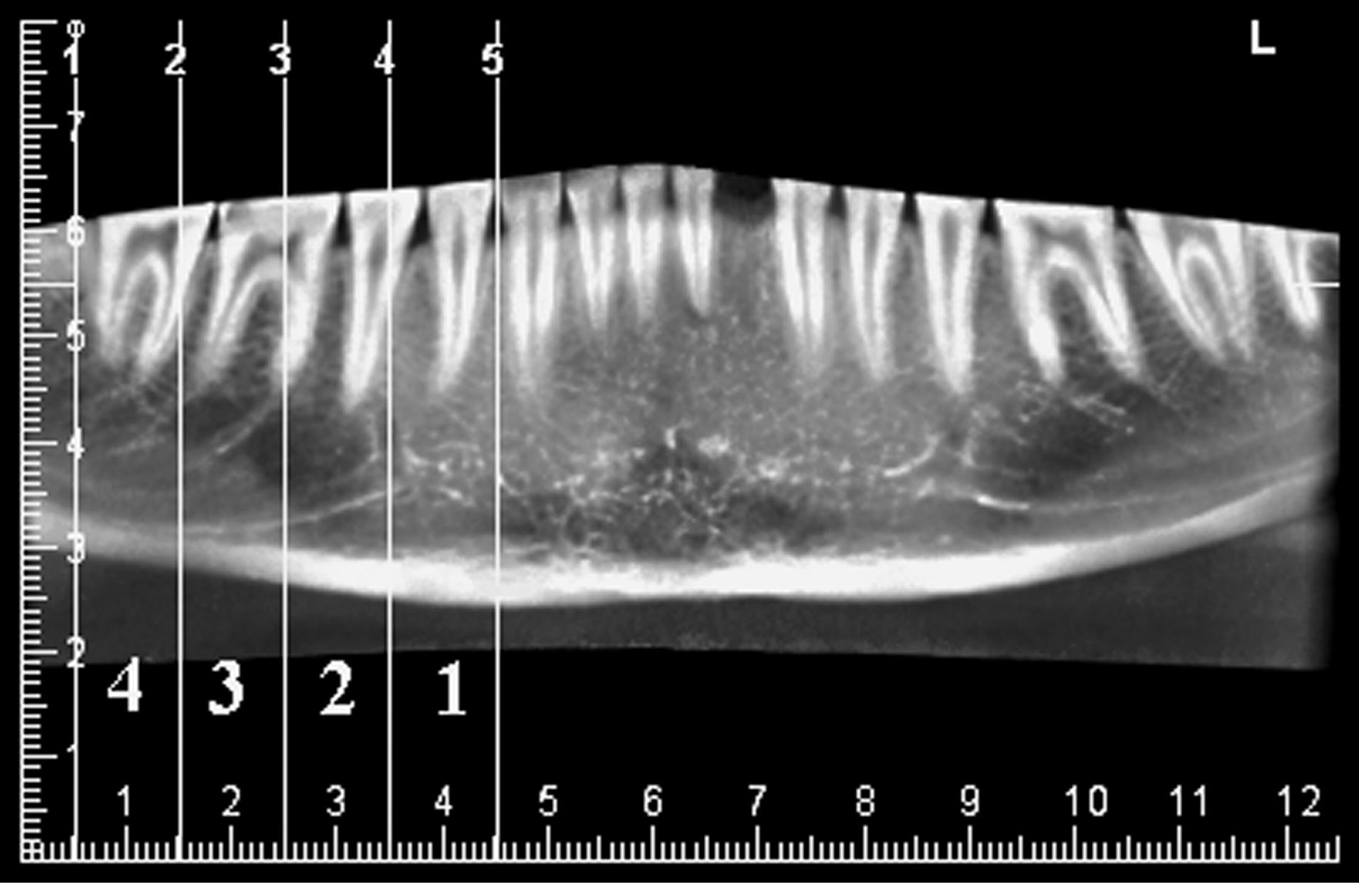
Figure 2.
A Cone-Beam Computed Tomography Reformatted Panoramic Image. Note. Five parallel lines divide the mandible into four regions with equal width (1cm)
.
A Cone-Beam Computed Tomography Reformatted Panoramic Image. Note. Five parallel lines divide the mandible into four regions with equal width (1cm)
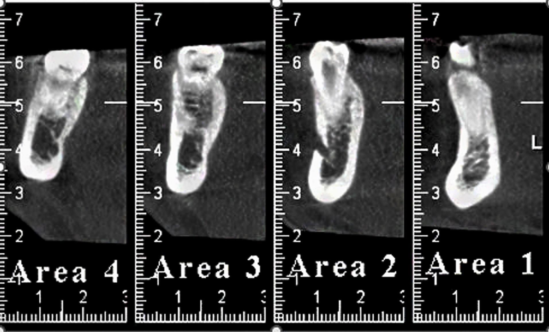
Figure 3.
Cone-Beam Computed Tomography Cross-sectional Images of 4 Areas With a Thickness of 0.5 mm
.
Cone-Beam Computed Tomography Cross-sectional Images of 4 Areas With a Thickness of 0.5 mm
Scoring System
The visibility of the superior and inferior borders of the IAC was evaluated using a binary scoring system, categorized as follows:
This binary scoring system was selected for its simplicity and clarity, ensuring a straightforward and consistent evaluation of visibility. This approach directly focuses on the visibility of the IAC borders. It aligns with the study’s core objective, which is to compare the presence or absence of visibility across different radiographic modalities.
Examiner Training and Evaluation
Three maxillofacial radiologists, each with a minimum of 10 years of experience, independently and randomly assessed the CBCT and panoramic radiographs, which were provided in JPEG format and devoid of identifiable information. Each examiner underwent individual training to familiarize themselves with the prescribed methodologies. CP, CRP, and CBCT cross-sectional (CCS) images were evaluated.
Interobserver Agreement
To ensure reliability, interobserver agreement was assessed using the Kappa statistic. The Kappa value was calculated to measure the consistency among the three examiners in scoring the visibility of the IAC borders.
Data Analysis
All data were analyzed using IBM SPSS Statistics for Windows, version 26.0 (IBM Corp., Armonk, NY, USA). Generalized estimating equations and logistic models were employed to investigate the relationship between independent variables and visibility. The patient was considered the subject variable in this analysis, while section, border, and technique were considered within-subject variables. A correlation matrix was established with an exchangeable structure, and statistical significance was defined as a P value < 0.05.
Results
The imaging techniques (i.e., CP, CRP, and CCS images) demonstrated a statistically significant relationship with the visibility of the IAC across the four mandibular areas. This significant relationship indicates that the effectiveness of these radiographic techniques varies in depicting the IAC structure (Table 1).
Table 1.
Visibility of Mandibular Regions on CRP, CCS, and CP Images
|
Technique
|
Border
|
Area
|
Value
|
| CRP |
Superior border |
Area 1 (Anterior) |
288 (87.8%) |
| Area 2 |
263 (80.2%) |
| Area 3 |
266 (81.1%) |
| Area 4 (Posterior) |
266 (81.1%) |
| Inferior border |
Area 1 |
297 (90.5%) |
| Area 2 |
299 (91.2%) |
| Area 3 |
298 (90.0%) |
| Area 4 |
300 (91.5%) |
| CCS |
Superior border |
Area 1 |
294 (89.6%) |
| Area 2 |
285 (86.9%) |
| Area 3 |
296 (90.2%) |
| Area 4 |
293 (89.3%) |
| Inferior border |
Area 1 |
300 (91.5%) |
| Area 2 |
291 (88.7%) |
| Area 3 |
301 (91.8%) |
| Area 4 |
302 (92.1%) |
| CP |
Superior border |
Area 1 |
255 (77.7%) |
| Area 2 |
221 (67.4%) |
| Area 3 |
229 (69.8%) |
| Area 4 |
273 (83.2%) |
| Inferior border |
Area 1 |
273 (83.2%) |
| Area 2 |
271 (82.6%) |
| Area 3 |
283 (86.3%) |
| Area 4 |
303 (92.4%) |
Note. CBCT: Cone-beam computed tomography; CCS: CBCT cross-sectional; CRP: CBCT reformatted panoramic; CP: Conventional panoramic.
Interobserver Agreement
Interobserver agreement among the three maxillofacial radiologists was measured using the kappa statistic, yielding a value of 0.73. This value indicates substantial agreement, reflecting a high level of consistency in assessments of IAC border visibility across the different modalities.
Superior vs. Inferior Border Visibility
Across all three radiographic techniques, the visibility of the superior border of the IAC was consistently lower than that of the inferior border. This difference was statistically significant in all mandibular regions. Specifically, CP images exhibited the highest visibility for both borders in Area 4, with visibility rates of 83.2% for the superior border and 92.4% for the inferior border. CRP images demonstrated the highest visibility for the superior border in Area 1 (87.7%) and the inferior border in Area 4 (91.5%). Likewise, CCS images exhibited the greatest visibility in Area 4 for both borders, with 90.2% for the superior border and 92.1% for the inferior border (Table 1).
Visibility of Superior Border Across Areas
When comparing the visibility of the superior border across different mandibular areas, CP images showed the highest visibility in Area 4, whereas CRP images had the greatest visibility in Area 1. CCS images, however, did not show significant differences in visibility across the four areas (Table 2).
Table 2.
Comparison Between Areas in Terms of the Superior Border Visibility
|
Technique
|
Comparison Areas
|
OR
|
95% CI
|
P
Value
|
| CRP |
1 to 4 |
1.68 |
1.12-2.51 |
0.01 |
| 2 to 4 |
0.94 |
0.70-1.27 |
0.70 |
| 3 to 4 |
1.00 |
0.78-1.28 |
1.00 |
| 2 to 1 |
0.56 |
0.39-0.81 |
0.002 |
| 3 to 1 |
0.60 |
0.41-0.88 |
0.009 |
| CCS |
1 to 4 |
1.03 |
0.63-1.68 |
0.90 |
| 2 to 4 |
0.79 |
0.53-1.18 |
0.25 |
| 3 to 4 |
1.10 |
0.76-1.61 |
0.60 |
| 2 to 1 |
0.77 |
0.50-1.17 |
0.22 |
| 3 to 1 |
1.07 |
0.65-1.75 |
0.79 |
| CP |
1 to 4 |
0.70 |
0.50-0.99 |
0.04 |
| 2 to 4 |
0.42 |
0.30-0.57 |
< 0.001 |
| 3 to 4 |
0.47 |
0.36-0.60 |
< 0.001 |
| 2 to 1 |
0.59 |
0.47-0.75 |
< 0.001 |
| 3 to 1 |
0.66 |
0.50-0.89 |
0.005 |
Note. CBCT: Cone-beam computed tomography; CCS: CBCT cross-sectional; CRP: CBCT reformatted panoramic; CP: Conventional panoramic; OR: Odds ratio; CI: Confidence interval.
Visibility of Inferior Border Across Areas
For the inferior border, no significant difference was observed in visibility across different areas on CRP and CCS images. However, CP images revealed significantly higher visibility of the inferior border in Area 4 compared to other sites (Table 3).
Table 3.
Comparison Between Areas in Terms of Inferior Border Visibility
|
Technique
|
Comparison Areas
|
OR
|
95% CI
|
P
Value
|
| CRP |
1 to 4 |
0.89 |
0.55-1.44 |
0.65 |
| 2 to 4 |
0.96 |
0.65-1.42 |
0.85 |
| 3 to 4 |
0.93 |
0.73-1.17 |
0.53 |
| 2 to 1 |
1.07 |
0.71-1.61 |
0.72 |
| 3 to 1 |
1.03 |
0.65-1.63 |
0.87 |
| CCS |
1 to 4 |
0.92 |
0.53-1.60 |
0.77 |
| 2 to 4 |
0.68 |
0.44-1.05 |
0.08 |
| 3 to 4 |
0.96 |
0.64-1.44 |
0.84 |
| 2 to 1 |
0.73 |
0.45-1.17 |
0.19 |
| 3 to 1 |
1.04 |
0.61-1.75 |
0.88 |
| CP |
1 to 4 |
0.41 |
0.26-0.64 |
< 0.001 |
| 2 to 4 |
0.39 |
0.26-0.59 |
< 0.001 |
| 3 to 4 |
0.52 |
0.37-0.73 |
< 0.001 |
| 2 to 1 |
0.95 |
0.72-1.25 |
0.75 |
| 3 to 1 |
1.26 |
0.91-1.75 |
0.15 |
Note. CBCT: Cone-beam computed tomography; CCS: CBCT cross-sectional; CRP: CBCT reformatted panoramic; CP: Conventional panoramic; OR: Odds ratio; CI: Confidence interval.
Visibility of Superior Border Across Modalities
Examining the visibility of the superior border across the three radiographic modalities, indicated that CCS and CRP images consistently provide higher visibility than CP images in Areas 1, 2, and 3. Specifically, in Areas 2 and 3, CCS images demonstrated significantly higher visibility than CRP images, while no significant difference was found between CRP and CCS images in Area 1. In Area 4, CP and CRP images exhibited similar visibility levels, but CCS images showed significantly higher visibility compared to both CP and CRP images (Table 4).
Table 4.
Comparison Between Different Radiographic Modalities in Terms of the Superior Border Visibility
|
Visibility
|
Technique
|
OR
|
95% CI
|
P
Value
|
| Area 1 |
CRP to CP |
2.06 |
1.43-2.95 |
< 0.001 |
| CCS to CP |
2.47 |
1.70-3.59 |
< 0.001 |
| CRP to CCS |
1.20 |
0.76-1.88 |
0.42 |
| Area 2 |
CRP to CP |
1.95 |
1.50-2.55 |
< 0.001 |
| CCS to CP |
3.20 |
2.31-4.45 |
< 0.001 |
| CRP to CCS |
1.63 |
1.15-2.31 |
0.005 |
| Area 3 |
CRP to CP |
1.85 |
1.41-2.43 |
< 0.001 |
| CCS to CP |
3.99 |
2.82-5.66 |
< 0.001 |
| CRP to CCS |
2.15 |
1.46-3.18 |
< 0.001 |
| Area 4 |
CRP to CP |
0.86 |
0.62-1.19 |
0.37 |
| CCS to CP |
1.68 |
1.14-2.49 |
0.009 |
| CRP to CCS |
1.95 |
1.32-2.86 |
0.001 |
Note. CBCT: Cone-beam computed tomography; CCS: CBCT cross-sectional; CRP: CBCT reformatted panoramic; CP: Conventional panoramic; OR: Odds ratio; CI: Confidence interval.
Visibility of Inferior Border Across Modalities
The visibility of the inferior border across different radiographic modalities indicated that CRP and CCS images generally provide higher visibility in Areas 1, 2, and 3 compared to CP images, with no significant difference between CRP and CCS. In Area 4, no significant difference was observed in visibility among the three modalities (Table 5).
Table 5.
Comparison Between Different Radiographic Modalities in Terms of Inferior Border Visibility
|
Visibility
|
Technique
|
OR
|
95% CI
|
P
Value
|
| Area 1 |
CRP to CP |
1.93 |
1.31-2.84 |
0.001 |
| CCS to CP |
2.15 |
1.45-3.19 |
< 0.001 |
| CRP to CCS |
1.11 |
0.69-1.80 |
0.64 |
| Area 2 |
CRP to CP |
2.16 |
1.54-3.04 |
< 0.001 |
| CCS to CP |
1.65 |
1.18-2.30 |
0.003 |
| CRP to CCS |
0.76 |
0.51-1.12 |
0.17 |
| Area 3 |
CRP to CP |
1.58 |
1.13-2.20 |
0.007 |
| CCS to CP |
1.77 |
1.20-2.60 |
0.004 |
| CRP to CCS |
1.12 |
0.70-1.77 |
0.62 |
| Area 4 |
CRP to CP |
0.88 |
0.58-1.34 |
0.56 |
| CCS to CP |
0.95 |
0.62-1.47 |
0.84 |
| CRP to CCS |
1.08 |
0.65-1.78 |
0.75 |
Note. CBCT: Cone-beam computed tomography; CCS: CBCT cross-sectional; CRP: CBCT reformatted panoramic; CP: Conventional panoramic; OR: Odds ratio; CI: Confidence interval.
Comparison of Superior and Inferior Border Visibility
The inferior border of the IAC consistently showed significantly higher visibility than the superior border across all three radiographic modalities in Areas 1 and 4. In Areas 2 and 3, the visibility of the superior border was significantly lower than that of the inferior border on both CRP and CP images. However, no statistically significant difference was found between the visibility of the superior and inferior borders on CCS images (Table 6).
Table 6.
Comparison Between the Superior and Inferior Border Visibility
|
Visibility
|
Technique
|
OR
|
95% CI
|
P
Value
|
| Area 1 |
CRP |
0.75 |
0.56-0.99 |
0.04 |
| CCS |
0.80 |
0.66-0.98 |
0.03 |
| CP |
0.70 |
0.59-0.83 |
< 0.001 |
| Area 2 |
CRP |
0.39 |
0.28-0.53 |
< 0.001 |
| CCS |
0.84 |
0.69-1.02 |
0.08 |
| CP |
0.43 |
0.34-0. 54 |
< 0.001 |
| Area 3 |
CRP |
0.43 |
0.32-0.57 |
< 0.001 |
| CCS |
0.83 |
0.66-1.03 |
0.09 |
| CP |
0.36 |
0.28-0.47 |
< 0.001 |
| Area 4 |
CRP |
0.40 |
0.29-0.54 |
< 0.001 |
| CCS |
0.72 |
0.57-0.91 |
0.006 |
| CP |
0.41 |
0.28-0.58 |
< 0.001 |
Note. CBCT: Cone-beam computed tomography; CCS: CBCT cross-sectional; CRP: CBCT reformatted panoramic; CP: Conventional panoramic; OR: Odds ratio; CI: Confidence interval.
Discussion
This study evaluated the visibility of the IAC using three different radiographic techniques: CP, CRP, and CCS images. Our findings revealed a statistically significant relationship between the type of radiographic modality and the visibility of the IAC, highlighting the varying effectiveness of these imaging techniques in visualizing the IAC structure.
Comparison of Radiographic Techniques
The results demonstrated that CCS images consistently provide superior visibility of both the superior and inferior borders of the IAC across most mandibular regions when compared to CP and CRP images. This is consistent with previous studies reporting that CBCT, particularly in cross-sectional views, offers enhanced visualization of delicate anatomical structures due to its three-dimensional imaging capability and higher spatial resolution (25). In contrast, while CP images are widely used due to their accessibility and lower radiation dose, they were found to be less effective in visualizing the IAC, especially the superior border. These findings align with earlier research documenting the limitations of panoramic radiography in depicting structures such as the IAC, especially in complex cases (25). Notably, Kamrun et al demonstrated superior visibility of the IAC borders on CBCT images compared to panoramic radiographs (7). Another study comparing CRP and CP indicated significantly higher visibility in all regions on CRP images compared to CP images (26).
Superior vs. Inferior Border Visibility
The key finding of this study was the consistently lower visibility of the superior border compared to the inferior border across all modalities. This disparity was most pronounced in CP and CRP images, where the visibility of the superior border was significantly less than that of the inferior border in multiple mandibular areas. This may be attributed to anatomical factors such as a higher presence of accessory branches in the superior border area compared to the inferior border, which can complicate its clear distinction, particularly in two-dimensional imaging modalities such as panoramic radiography (26). The greater visibility of the inferior border compared to the superior border is consistent with results from previous studies (3,27,28).
The visibility of both borders was notably higher on CCS images, especially in Areas 2 and 3, where CBCT provided significantly clearer images compared to CP and CRP. The superior visibility of the inferior border on CP images, particularly in Area 4, may be related to its anatomical location and the imaging characteristics of CP radiographs, where certain regions of the mandible are more favorably represented. Furthermore, anatomical variations and changes in the pathway of the mandibular canal could also contribute to this superiority of visibility. Specifically, the canal tends to move toward the buccal side before opening in the mental foramen, making the anterior part less visible (3,27).
Interobserver Agreement
The kappa statistic of 0.73 obtained in this study indicates substantial agreement among the three experienced maxillofacial radiologists, underscoring the reliability of the visibility assessments. This level of agreement is crucial for ensuring that the findings are not significantly influenced by observer variability, thereby strengthening the validity of the study’s results.
Comparison of Visibility in Different Areas
Our study revealed that Area 2 (around the mental foramen) exhibits lower visibility compared to other areas. This finding is consistent with that of the study by Santos et al who noted that while cross-sectional imaging is generally more effective in displaying the mandibular canal, visibility in the region near the mental foramen remains challenging due to superimposition of adjacent structures and the thinner mandibular cortex (29).
Areas 1 (anterior) and 4 (posterior) showed significantly higher visibility than Areas 2 and 3, with Area 4 displaying slightly better visibility than Area 1; however, this difference was not statistically significant. Additionally, Area 3 was significantly more visible than Area 2, consistent with the study by Angelopoulos et al, who found that the IAC in the posterior region is significantly more visible due to the thicker mandibular cortex compared to the anterior regions (3).
For the inferior border, Area 4 exhibited significantly higher visibility than other regions, which is consistent with previous studies (3,7). Starkie et al and Gowgiel reported that the presence of a compact bone sheath in the posterior region, along with the contact of the neurovascular bundle with the lingual cortical plate, contributed to the improved visibility in this area (30,31).
Overall, CBCT cross-sectional and CRP images demonstrated significantly higher visibility of both borders compared to panoramic images, with no significant difference between CCS and CRP images. The enhanced visibility in CBCT is largely attributed to its 3D nature, which reduces superimposition and distortion encountered in 2D imaging modalities.
Clinical Implications
The findings of this study hold significant clinical implications, particularly for pre-surgical planning for dental implants, where accurate visualization of the IAC is critical to avoid nerve injury (12). The superior performance of CCS images suggests that CBCT should be the imaging modality of choice in cases where precise visualization of the IAC is required. However, it is essential to balance the need for detailed imaging with considerations of radiation exposure, especially in younger patients or those requiring multiple scans (24).
Study Limitations
Several limitations of this study should be acknowledged. First, the study was conducted retrospectively and relied on radiographic records from a single Iranian institution, which may limit the generalizability of the findings to other populations or clinical settings. Furthermore, although the sample size was adequate, the study did not account for potential confounding factors such as age and gender, which could influence the visibility of the IAC. Moreover, the study utilized a specific radiographic technique (Planmeca ProMax) and software (Planmeca ProMax 3D), which may limit the generalizability of the findings to other radiographic systems and software packages used in clinical practice.
Future research should aim to validate these findings through a prospective multicenter study with a larger and more diverse population. Additionally, evaluating the IAC visibility using different radiographic systems and software packages would help determine whether the findings are consistent across various technologies.
Conclusion
This study clearly demonstrates that CBCT images, particularly cross-sectional CBCT, provide superior visibility of the IAC in anterior regions and along the upper border compared to CP techniques. Across all areas and imaging modalities, the upper border of the canal consistently exhibits lower visibility than the lower border. For pre-implant surgery evaluations, cross-sectional CBCT is recommended for assessing the upper canal border, while both CBCT techniques are equally effective in visualizing the lower border. Panoramic radiography shows comparable success in posterior regions. These findings underscore the critical role of selecting appropriate imaging modalities based on clinical needs, with CCS images proving invaluable for detailed anatomical visualization.
Authors’ Contribution
Conceptualization: Daryoush Goodarzipour, Farzaneh Mosavat, Mohammad Saleh Fahimzad, Mahsa Bayati.
Data curation: Daryoush Goodarzipour, Farzaneh Mosavat, Mahsa Bayati.
Formal analysis: Daryoush Goodarzipour, Farzaneh Mosavat, Mahsa Bayati.
Funding acquisition: Daryoush Goodarzipour, Mohammad Saleh Fahimzad, Mahsa Bayati.
Investigation: Daryoush Goodarzipour, Farzaneh Mosavat, Mahsa Bayati.
Methodology: Daryoush Goodarzipour, Farzaneh Mosavat.
Project administration: Daryoush Goodarzipour, Mahsa Bayati.
Resources: Daryoush Goodarzipour, Mahsa Bayati.
Software: Daryoush Goodarzipour, Mohammad Saleh Fahimzad, Mahsa Bayati.
Supervision: Daryoush Goodarzipour, Farzaneh Mosavat.
Validation: Daryoush Goodarzipour, Farzaneh Mosavat, Mohammad Saleh Fahimzad, Mahsa Bayati.
Visualization: Daryoush Goodarzipour, Mohammad Saleh Fahimzad, Mahsa Bayati.
Writing–original draft: Daryoush Goodarzipour, Mohammad Saleh Fahimzad, Mahsa Bayati.
Writing–review & editing: Farzaneh Mosavat, Mahsa Bayati.
Competing Interests
The authors declare no potential conflict of interests with respect to the research, authorship, and publication of this study.
Data Availability Statement
The data are accessible from the corresponding author upon reasonable request.
Ethical Approval
This study was approved by the Ethics Committee of Tehran University of Medical Sciences (IR.TUMS.DENTISTRY.REC.1396.2283).
Funding
This research received no specific grant from public, commercial, or not-for-profit funding agencies.
References
- Jacobs R, Mraiwa N, Van Steenberghe D, Sanderink G, Quirynen M. Appearance of the mandibular incisive canal on panoramic radiographs. Surg Radiol Anat 2004; 26(4):329-33. doi: 10.1007/s00276-004-0242-2 [Crossref] [ Google Scholar]
- Juodzbalys G, Wang HL, Sabalys G. Anatomy of mandibular vital structures Part I: mandibular canal and inferior alveolar neurovascular bundle in relation with dental implantology. J Oral Maxillofac Res 2010; 1(1):e2. doi: 10.5037/jomr.2010.1102 [Crossref] [ Google Scholar]
- Angelopoulos C, Thomas SL, Hechler S, Parissis N, Hlavacek M. Comparison between digital panoramic radiography and cone-beam computed tomography for the identification of the mandibular canal as part of presurgical dental implant assessment. J Oral Maxillofac Surg 2008; 66(10):2130-5. doi: 10.1016/j.joms.2008.06.021 [Crossref] [ Google Scholar]
- Cartes G, Garay I, Deana NF, Navarro P, Alves N. Mandibular canal course and the position of the mental foramen by panoramic X-ray in Chilean individuals. Biomed Res Int 2018; 2018:2709401. doi: 10.1155/2018/2709401 [Crossref] [ Google Scholar]
- Wadu SG, Penhall B, Townsend GC. Morphological variability of the human inferior alveolar nerve. Clin Anat 1997; 10(2):82-7. doi: 10.1002/(sici)1098-2353(1997)10:2<82::aid-ca2>3.0.co;2-v [Crossref] [ Google Scholar]
- Aoun G. Visibility of the mandibular canal: from two-dimensional radiography to three-dimensional imaging. SciELO [Preprint]. June 13, 2022. Available from: https://preprints.scielo.org/index.php/scielo/preprint/view/4263.
- Kamrun N, Tetsumura A, Nomura Y, Yamaguchi S, Baba O, Nakamura S. Visualization of the superior and inferior borders of the mandibular canal: a comparative study using digital panoramic radiographs and cross-sectional computed tomography images. Oral Surg Oral Med Oral Pathol Oral Radiol 2013; 115(4):550-7. doi: 10.1016/j.oooo.2013.01.001 [Crossref] [ Google Scholar]
- Parnia F, Moslehifard E, Hafezeqoran A, Mahboub F, Mojaver-Kahnamoui H. Characteristics of anatomical landmarks in the mandibular interforaminal region: a cone-beam computed tomography study. Med Oral Patol Oral Cir Bucal 2012; 17(3):e420-5. doi: 10.4317/medoral.17520 [Crossref] [ Google Scholar]
- von Arx T, Bornstein MM. The bifid mandibular canal in three-dimensional radiography: morphologic and quantitative characteristics. Swiss Dent J 2021; 131(1):10-28. doi: 10.61872/sdj-2021-01-01 [Crossref] [ Google Scholar]
- Naitoh M, Katsumata A, Kubota Y, Hayashi M, Ariji E. Relationship between cancellous bone density and mandibular canal depiction. Implant Dent 2009; 18(2):112-8. doi: 10.1097/ID.0b013e318198da7e [Crossref] [ Google Scholar]
- Shokry SM, Alshaib SA, Al Mohaimeed ZZ, Ghanimah F, Altyebe MM, Alenezi MA. Assessment of the inferior alveolar nerve canal course among Saudis by cone beam computed tomography (pilot study). J Maxillofac Oral Surg 2019; 18(3):452-8. doi: 10.1007/s12663-018-1167-3 [Crossref] [ Google Scholar]
- Juodzbalys G, Wang HL, Sabalys G. Injury of the inferior alveolar nerve during implant placement: a literature review. J Oral Maxillofac Res 2011; 2(1):e1. doi: 10.5037/jomr.2011.2101 [Crossref] [ Google Scholar]
- Tantanapornkul W, Okouchi K, Fujiwara Y, Yamashiro M, Maruoka Y, Ohbayashi N. A comparative study of cone-beam computed tomography and conventional panoramic radiography in assessing the topographic relationship between the mandibular canal and impacted third molars. Oral Surg Oral Med Oral Pathol Oral Radiol Endod 2007; 103(2):253-9. doi: 10.1016/j.tripleo.2006.06.060 [Crossref] [ Google Scholar]
- Lou L, Lagravere MO, Compton S, Major PW, Flores-Mir C. Accuracy of measurements and reliability of landmark identification with computed tomography (CT) techniques in the maxillofacial area: a systematic review. Oral Surg Oral Med Oral Pathol Oral Radiol Endod 2007; 104(3):402-11. doi: 10.1016/j.tripleo.2006.07.015 [Crossref] [ Google Scholar]
- Kamburoğlu K, Kiliç C, Ozen T, Yüksel SP. Measurements of mandibular canal region obtained by cone-beam computed tomography: a cadaveric study. Oral Surg Oral Med Oral Pathol Oral Radiol Endod 2009; 107(2):e34-42. doi: 10.1016/j.tripleo.2008.10.012 [Crossref] [ Google Scholar]
- Lofthag-Hansen S, Gröndahl K, Ekestubbe A. Cone-beam CT for preoperative implant planning in the posterior mandible: visibility of anatomic landmarks. Clin Implant Dent Relat Res 2009; 11(3):246-55. doi: 10.1111/j.1708-8208.2008.00114.x [Crossref] [ Google Scholar]
- Scarfe WC, Farman AG, Sukovic P. Clinical applications of cone-beam computed tomography in dental practice. J Can Dent Assoc 2006; 72(1):75-80. [ Google Scholar]
- Small BW. Cone beam computed tomography. Gen Dent 2007; 55(3):179-81. [ Google Scholar]
- Venkatesh E, Elluru SV. Cone beam computed tomography: basics and applications in dentistry. J Istanb Univ Fac Dent 2017; 51(3 Suppl 1):S102-21. doi: 10.17096/jiufd.00289 [Crossref] [ Google Scholar]
- Saif N, El-Beialy AR. The effect of voxel size on the reliability and reproducibility of alveolar bone crest identification on cone beam CT scans. Egypt Dent J 2018; 64(2):1215-26. doi: 10.21608/edj.2018.77375 [Crossref] [ Google Scholar]
- Mosavat F, Ahmadi E, Amirfarhangi S, Rafeie N. Evaluation of diagnostic accuracy of CBCT and intraoral radiography for proximal caries detection in the presence of different dental restoration materials. BMC Oral Health 2023; 23(1):419. doi: 10.1186/s12903-023-02954-8 [Crossref] [ Google Scholar]
- Shah N, Bansal N, Logani A. Recent advances in imaging technologies in dentistry. World J Radiol 2014; 6(10):794-807. doi: 10.4329/wjr.v6.i10.794 [Crossref] [ Google Scholar]
- Noujeim M, Prihoda T, McDavid WD, Ogawa K, Yamakawa T, Seki K. Pre-clinical evaluation of a new dental panoramic radiographic system based on tomosynthesis method. Dentomaxillofac Radiol 2011; 40(1):42-6. doi: 10.1259/dmfr/73312141 [Crossref] [ Google Scholar]
- Lofthag-Hansen S, Thilander-Klang A, Ekestubbe A, Helmrot E, Gröndahl K. Calculating effective dose on a cone beam computed tomography device: 3D accuitomo and 3D accuitomo FPD. Dentomaxillofac Radiol 2008; 37(2):72-9. doi: 10.1259/dmfr/60375385 [Crossref] [ Google Scholar]
- Cederhag J, Truedsson A, Alstergren P, Shi XQ, Hellén-Halme K. Radiographic imaging in relation to the mandibular third molar: a survey among oral surgeons in Sweden. Clin Oral Investig 2022; 26(2):2073-83. doi: 10.1007/s00784-021-04189-9 [Crossref] [ Google Scholar]
- Panjnoush M, Rabiee ZS, Kheirandish Y. Assessment of location and anatomical characteristics of mental foramen, anterior loop and mandibular incisive canal using cone beam computed tomography. J Dent (Tehran) 2016; 13(2):126-32. [ Google Scholar]
- Nemati S, Ashouri Moghadam A, Dalili Kajan Z, Mohtavipour ST, Amouzad H. An analysis of visibility and anatomic variations of mandibular canal in digital panoramic radiographs of dentulous and edentulous patients in Northern Iran populations. J Dent (Shiraz) 2016; 17(2):112-20. [ Google Scholar]
- Pria CM, Masood F, Beckerley JM, Carson RE. Study of the inferior alveolar canal and mental foramen on digital panoramic images. J Contemp Dent Pract 2011; 12(4):265-71. doi: 10.5005/jp-journals-10024-1045 [Crossref] [ Google Scholar]
- Oliveira-Santos C, Capelozza AL, Dezzoti MS, Fischer CM, Poleti ML, Rubira-Bullen IR. Visibility of the mandibular canal on CBCT cross-sectional images. J Appl Oral Sci 2011; 19(3):240-3. doi: 10.1590/s1678-77572011000300011 [Crossref] [ Google Scholar]
- Gowgiel JM. The position and course of the mandibular canal. J Oral Implantol 1992; 18(4):383-5. [ Google Scholar]
- Starkie C, Stewart D. The intra-mandibular course of the inferior dental nerve. J Anat 1931; 65(Pt 3):319-23. [ Google Scholar]