Avicenna J Dent Res. 13(2):57-61.
doi: 10.34172/ajdr.2021.11
Original Article
Stress Distribution in Implant-Supported Overdenture and Peri-Implant Bone Using Three Attachment Systems: A Finite Element Analysis
Alireza Izadi 1, *  , Fariboorz Vafaie 2, Armaghan Shahbazi 3, Mohamad Taghi Mokri vala 4
Author information:
1Department of Prosthodontics, Faculty of Dentistry, Hamedan University of Medical Sciences, Hamedan, Iran.
2Dental Implants Research Center, Faculty of Dentistry, Hamedan University of Medical Sciences, Hamadan, Iran.
3Prosthodontic Department, Faculty of Dentistry, Tehran Medical Sciences, Islamic Azad University, Tehran, Iran.
4Dentist, Hamedan University of medical Sciences, Hamedan, Iran.
Abstract
Background: This finite element analysis (FEA) evaluated stress distribution in implant-supported overdenture (ISO) and peri-implant bone using one extracoronal (ball) and two intracoronal (locator and Zest Anchor Advanced Generation (ZAAG)) attachment systems.
Methods: In this in vitro study, the mandible was modelled in the form of an arc-shaped bone block with 33 mm height and 8 mm width. Two titanium implants were modelled at the site of canine teeth, and three attachments (ZAGG, locator, and ball) were placed over them. Next, 100 N load was applied at 90° and 30° angles from the molar site of each quadrant to the implants. The stress distribution pattern in the implants and the surrounding bone was analyzed, and the von Mises stress around the implants and in the crestal bone was calculated.
Results: While minimum stress in peri-implant bone following load application at 30° angle was noted in the mesial point of the locator attachment, maximum stress was recorded at the distal point of the ball attachment following load application at 90° angle. Maximum stress around the implant following load application at 90° angle was noted in the lingual point of the ball attachment while minimum stress was recorded in the lingual point of the locator attachment following load application at 90° angle.
Conclusions: According to the results, the locator attachment is preferred to the ZAAG attachment, and the ball attachment should be avoided if possible.
Keywords: Attachment, Overdenture, Finite element analysis
Copyright and License Information
© 2021 The Author(s); Published by Hamadan University of Medical Sciences.
This is an open-access article distributed under the terms of the Creative Commons Attribution License (
http://creativecommons.org/licenses/by/4.0), which permits unrestricted use, distribution, and reproduction in any medium provided the original work is properly cited.
Citation: Izadi A, Vafaie F, Shahbazi A, Mokri Vala MT. Stress Distribution in Implant-Supported Overdenture and Peri-Implant Bone Using Three Attachment Systems: A Finite Element Analysis. Avicenna J Dent Res. 2021;13(2):57-61. doi: 10.34172/ajdr.2021.11.
Background
Highlights
Implant-supported overdenture (ISO) is an efficient treatment plan due to its simplicity, non-invasiveness, and affordability (1,2). It is particularly suitable for patients who are not satisfied with their complete dentures. Overdentures are preferred for use in patients with severe resorption of the alveolar ridge or those who cannot afford placement of several dental implants. Different attachment systems are used to connect implants to overdentures such as the bar, ball, and magnet attachment systems (3,4). Using implants to support the overdenture significantly increases its retention and stability. Biomechanical factors play an important role in preservation of the peri-implant bone. Loads applied to the overdenture are transferred to the implants and subsequently to the peri-implant bone. Bone tissue undergoes remodeling in response to mechanical loads. The stresses applied through the implants to the bone may be constructive or destructive. Very low stress can lead to disuse atrophy of bone while excessive pressure can cause compression necrosis and subsequent implant failure (5,6). ISOs should be designed such that they uniformly distribute the stress to implants and peri-implant bone (7-9).
Selection of the appropriate attachment type for overdenture is challenging for many prosthodontists because attachments transfer the stress and loads applied to the overdenture to the abutments, and subsequently to the bone (10,11). The generated stress is affected by a number of factors such as the type of load, the material of attachments, the design of attachments, and the quality of bone surrounding the abutments. Considering the increasing use of overdentures, selection of the appropriate attachment type can help benefit from the advantages of overdentures (12-14). The attachments increase the overdenture retention over the implants. However, they also transfer vertical and/or horizontal loads to the implants (15-17).
Several methods are available for assessment of stress distribution around dental implants such as photoblastic methods, finite element analysis (FEA), and measurement of strain in bone. FEA has advantages such as accurate reconstruction of complex geometrical shapes, enabling simple manipulation and alteration of patterns, and simulation of internal stress patterns and other mechanical quantities (18). Considering the gap of information regarding stress distribution patterns in use of intracoronal and extracoronal attachments following load application from different angles, this study aimed to assess stress distribution in ISO and peri-implant bone in use of three attachment types including one extracoronal (ball) and two intracoronal (locator and Zest Anchor Advanced Generation (ZAAG)) attachment systems using FEA.
Materials and Methods
This in vitro experimental FEA was conducted on three models. First, the mandible was modelled in the form of an arc-shaped bone block with 33 mm height and 8 mm width. Two titanium implants (D3 BioHorizons implant system) with 12 mm height and 3.8 mm diameter were modelled at the site of canine teeth in this block. The implants had 8 mm distance from the midline. Three models were designed for the three attachment systems. The Zest Anchor Advanced Generation (ZAAG) intracoronal attachment system (Zest Anchor, CA, USA) was used on implants bilaterally in the first model. The locator intracoronal attachment system (Zest Anchor, CA, USA) was used on implants bilaterally in the second model; and the ball extracoronal attachment (Rhein 83; Bologna, Italy) was used bilaterally on implants in the third model. An overdenture with 0.5 mm height from the ridge crest was placed over the attachments.
Characteristics of the Attachments
ZAAG attachment (Zest Anchor, CA, USA): Length of male component: 2.7 mm, diameter of male component: 4.2 mm, abutment thread height: 2.9 mm, thread radius: 1.1 mm
Locator attachment (Zest Anchor, CA, USA): Length of male component: 1.35 mm, diameter of male component: 2.1 mm, length of female component: 2 mm, diameter of female component: 0.52, cap height: 1 mm.
Ball attachment (Rhein 83, Bologna, Italy): Length of male component: 2.85 mm, diameter of male component: 1.2 mm, diameter of cap: 5 mm, length of cap: 2.5 mm
The ABAQUS software was used to design the geometrical shapes. A total of 45 solid elements were used for all items with three degrees of freedom for stress calculation. Similar to previous studies, the Poisson’s ratio and the modulus of elasticity were used for better simulation of clinical setting by the models.
The jawbone was divided into two segments: the top 3 mm of crestal bone was considered as the cortical bone while the rest of the bone block (to the bottom) was composed of spongy bone. It should be noted that all modeled materials were isotropic, homogenous, and linearly elastic.
In this study, the number of elements and nodes was about 30 000 and 40 000, respectively based on previous studies. Eventually, 100 N load was applied to the models at 30° and 90° angles. The loads were applied from the site of molar teeth at each quadrant. Next, the stress distribution pattern in implants and peri-implant bone was analyzed. The von Mises stress around the implants and in the crestal bone was also calculated.
Results
The von Mises stress in all three models at the buccal, lingual, mesial, and distal points of the implant platform and crestal bone was calculated following load application at 30° and 90° angles.
Comparison of the von Mises stress in the peri-implant bone in use of the three attachment types revealed maximum stress in the ball attachment (6598) followed by the ZAAG (5455) and locator (4760) attachments after load application at 90° angle.
Maximum stress was noted in the ball attachment (6254) followed by the ZAAG (5330) and locator (4551) attachments after load application at 30° angle.
Comparison of the von Mises stress in the implants in the three attachment systems revealed maximum stress in the ball attachment followed by the locator and ZAAG attachments after load application at 90° angle. Maximum stress was noted in the ball attachment followed by the ZAAG and locator attachments after load application at 30° angle. Figure 1 compares the magnitude of stress in the peri-implant bone in the three attachment systems following load application at 30° and 90° angles.
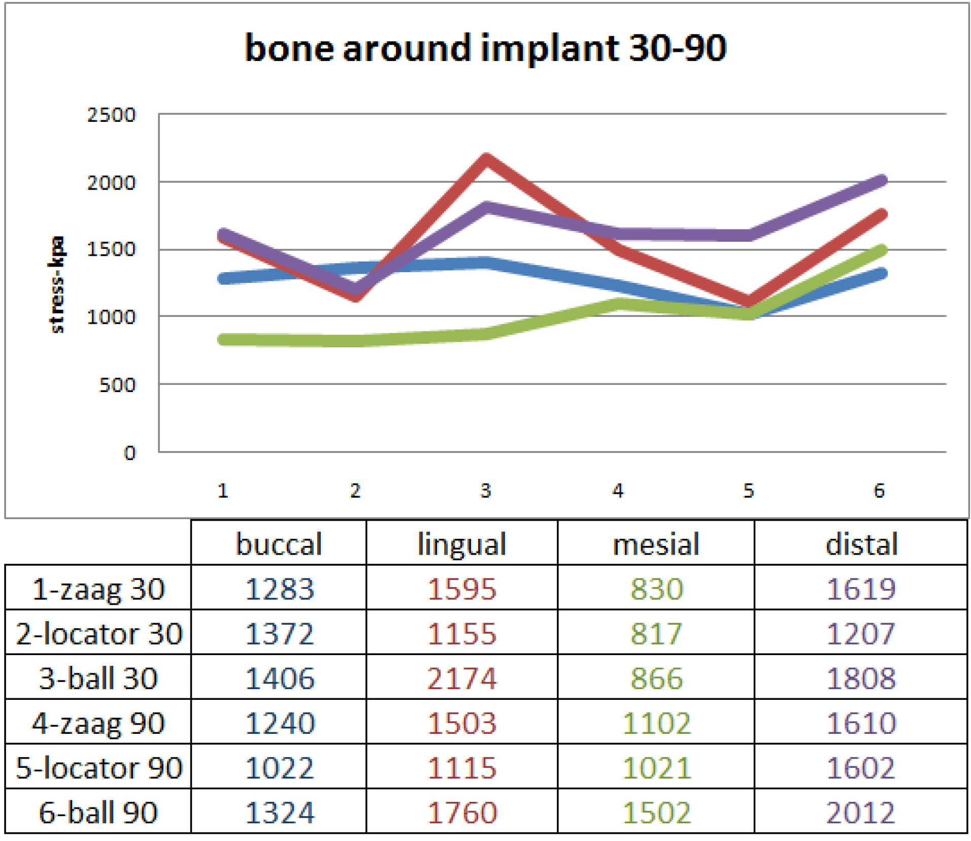
Figure 1.
Magnitude of Stress in the Peri-implant Bone in Use of the Three Attachment Systems Following Load Application at 30° and 90° Angles.
.
Magnitude of Stress in the Peri-implant Bone in Use of the Three Attachment Systems Following Load Application at 30° and 90° Angles.
Comparison of stress in the peri-implant bone in the three attachment systems following load application at 30° and 90° angles revealed minimum stress at the mesial point of the locator attachment following load application at 30° angle; meanwhile, maximum stress was noted at the distal point of the ball attachment following load application at 90° angle (Figure 1).
While the load application at 30° and 90° angles revealed maximum stress at the lingual point of the ball attachment following the application of 100 N load at 90° angle, minimum stress was noted at the lingual point of the locator attachment following load application at 90° angle (Figure 2).
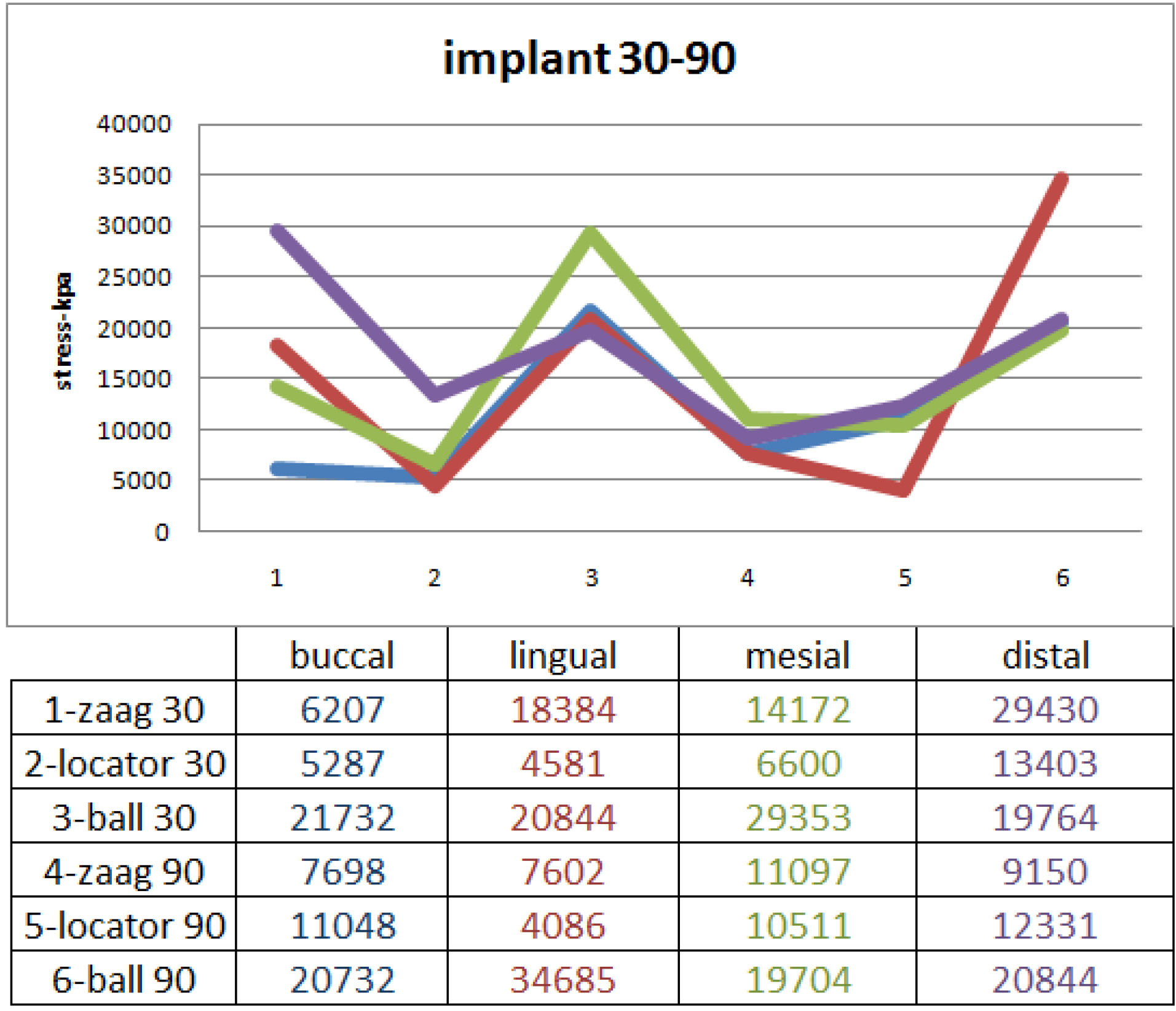
Figure 2.
Comparison of Stress in the Implants in use of the Three Attachment Systems Following Load Application at 30° and 90° Angles.
.
Comparison of Stress in the Implants in use of the Three Attachment Systems Following Load Application at 30° and 90° Angles.
Assessment of stress at different points of the three attachment systems revealed that all three attachment systems had maximum stress accumulation at their distal point. Minimum stress was noted at the mesial point of the locator and ZAAG attachments and at the buccal point of the ball attachment.
Discussion
This FEA evaluated three overdenture attachment systems including one extracoronal and two intracoronal implant attachments. Considering the pattern of von Mises stress distribution at the four points of buccal, lingual, mesial, and distal of the ZAAG (Model 1), locator (Model 2), and ball (Model 3) attachments and in peri-implant bone following load application at 30° and 90° angles, the following results were obtained:
-
The ball attachment transferred greater stress to the implants and the peri-implant bone at all points and at both load application angles.
-
The locator attachment transferred lower level of stress to the implants and the peri-implant bone compared with the other two attachments at both load application angles.
-
A higher level of stress was recorded at all points following load application at 30° angle compared with 90° angle.
-
A higher level of stress was noted in the peri-implant bone and lingual point of all attachments in load application at 30° angle compared with 90° angle.
-
In total, the level of stress transferred to the implants was greater than the level of stress transferred to the bone, especially in the lingual region.
Our findings were similar to those of Ibrahim and Radi (19) in Cairo University. They assessed the changes in bone and peri-implant bone atrophy in 14 completely edentulous patients using ball and locator attachments. After 18 months, the bone loss in patients who had the ball attachment indicated a higher level of stress in the ball attachment compared with the locator attachment. Also, the level of stress in both ball and locator attachments was greater at the distal compared with the mesial surface, which indicates higher stress accumulation at the distal point. This finding was in agreement with our results. El-Anwar et al (20) evaluated the effects of number of implants and attachment type on stress distribution in ISO of the mandible and concluded that the attachment deformity and stress distribution in the locator attachment were insignificant compared with the ball attachment. This finding indicates higher survival rate and less need for repair of this attachment. Their results were in accordance with our findings. Similarly, El-Anwar et al (21) reported that the level of stress applied to the peri-implant bone was greater at the distal compared with the mesial surface. Cakarer et al (22) reported that 14 patients were dissatisfied with the ball attachment, and seven patients were dissatisfied with the bar attachment. However, no dissatisfaction with the locator attachment was reported. They concluded that use of locator attachment is associated with higher patient satisfaction; their findings were in accordance with our results.
Saboori et al (23) found that overdentures with the bar attachment experienced greater stress following vertical load application to both the implant at the side of load application and the contralateral implant compared with other attachment systems. The level of stress in implants was greater in oblique load application than vertical load application. In use of ball and ZAAG attachments, stress was applied to the implants and the edentulous ridge following vertical load application. However, in oblique load application, greater stress was applied to the implants while no stress was recorded in the edentulous ridge. The bar attachment transfers greater stress to the implants following vertical and oblique load applications compared with the ball and ZAAG attachments. Comparison of the ball and ZAAG attachments revealed that the ZAAG attachment transferred greater stress to the implant body compared with the ball attachment, which was different from our findings; this controversy may be due to the different directions of load application.
Mericske-Stern and Zarb (4) performed a piezoelectric test and observed that vertical load application resulted in greater stress in the implant body in use of a single telescopic attachment compared with the ball attachment, which was inconsistent with our findings. Such a controversy in the results can be due to the different designs or applied loads.
Our literature review yielded no study comparing the ball, ZAAG, and locator attachments to compare our results with. The majority of previous studies focused on ball attachment or compared two attachment systems.
Conclusions
Within the limitations of this study, it may be concluded that the locator attachment (Model 2) is preferred to the ZAAG attachment (Model 1) for ISOs in terms of stress distribution, and the ball attachment (Model 3) should be avoided if possible.
Conflict of Interest Disclosures
The authors declare that they have no conflict of interests.
Ethical Statement
The Research Ethics Committee of Hamadan University of Medical Sciences approved this study.
Authors’ Contribution
AI: Conceived and designed the analysis, supervised the paper
FV, AS: Conceived and designed the analysis; collected the data; contributed data or analysis tools; wrote the paper
MTMV: performed the analysis; wrote the paper.
References
- Johns RB, Jemt T, Heath MR, Hutton JE, McKenna S, McNamara DC. A multicenter study of overdentures supported by Brånemark implants. Int J Oral Maxillofac Implants 1992; 7(4):513-22. [ Google Scholar]
- Araby YA, Agamy EM. Implant stability and marginal bone loss in mandibular implant retained overdenture cases: a comparative study using two stud attachment systems. Egypt Dent J 2016; 62(1):1065-73. doi: 10.21608/edj.2016.95420 [Crossref] [ Google Scholar]
- Nyström E, Ahlqvist J, Gunne J, Kahnberg KE. 10-year follow-up of onlay bone grafts and implants in severely resorbed maxillae. Int J Oral Maxillofac Surg 2004; 33(3):258-62. doi: 10.1006/ijom.2003.0512 [Crossref] [ Google Scholar]
- Mericske-Stern R, Zarb GA. Overdentures: an alternative implant methodology for edentulous patients. Int J Prosthodont 1993; 6(2):203-8. [ Google Scholar]
- Raghoebar GM, Meijer HJ, Stegenga B, van’t Hof MA, van Oort RP, Vissink A. Effectiveness of three treatment modalities for the edentulous mandible A five-year randomized clinical trial. Clin Oral Implants Res 2000; 11(3):195-201. doi: 10.1034/j.1600-0501.2000.011003195.x [Crossref] [ Google Scholar]
- Geertman ME, van Waas MA, van ‘t Hof MA, Kalk W. Denture satisfaction in a comparative study of implant-retained mandibular overdentures: a randomized clinical trial. Int J Oral Maxillofac Implants 1996; 11(2):194-200. [ Google Scholar]
- Bilhan H, Geckili O, Mumcu E, Bilmenoglu C. Maintenance requirements associated with mandibular implant overdentures: clinical results after first year of service. J Oral Implantol 2011; 37(6):697-704. doi: 10.1563/aaid-joi-d-10-00096 [Crossref] [ Google Scholar]
- Krennmair G, Seemann R, Fazekas A, Ewers R, Piehslinger E. Patient preference and satisfaction with implant-supported mandibular overdentures retained with ball or locator attachments: a crossover clinical trial. Int J Oral Maxillofac Implants 2012; 27(6):1560-8. [ Google Scholar]
- Hutton JE, Heath MR, Chai JY, Harnett J, Jemt T, Johns RB. Factors related to success and failure rates at 3-year follow-up in a multicenter study of overdentures supported by Brånemark implants. Int J Oral Maxillofac Implants 1995; 10(1):33-42. [ Google Scholar]
- Celik G, Uludag B. Photoelastic stress analysis of various retention mechanisms on 3-implant-retained mandibular overdentures. J Prosthet Dent 2007; 97(4):229-35. doi: 10.1016/j.prosdent.2007.02.006 [Crossref] [ Google Scholar]
- Fanuscu MI, Caputo AA. Influence of attachment systems on load transfer of an implant-assisted maxillary overdenture. J Prosthodont 2004; 13(4):214-20. doi: 10.1111/j.1532-849X.2004.04041.x [Crossref] [ Google Scholar]
- Alqutaibi AY, Kaddah AF. Attachments used with implant supported overdenture. Int Dent Med J Adv Res 2016; 2(1):1-5. doi: 10.15713/ins.idmjar.45 [Crossref] [ Google Scholar]
- Eltaftazani I, Moubarak A, El-Anwar M. Locator attachment versus ball attachment: 3-dimensional finite element study. Egypt Dent J 2011; 57:73-85. [ Google Scholar]
- Porter JA Jr, Petropoulos VC, Brunski JB. Comparison of load distribution for implant overdenture attachments. Int J Oral Maxillofac Implants 2002; 17(5):651-62. [ Google Scholar]
- Hatim NA, Al-Sheakh AM, Saeed SH. Satisfaction of Patient with Stud, Bar and Magnet Attachment Systems for Mandibular Two-Implant Over Dentures. Al-Rafidain Dental Journal 2013; 3(23):380-7. [ Google Scholar]
- Bilhan H, Geckili O, Sulun T, Bilgin T. A quality-of-life comparison between self-aligning and ball attachment systems for 2-implant-retained mandibular overdentures. J Oral Implantol 2011; 37 Spec No:167-73. doi: 10.1563/AAID-JOI-D-10-00070 [Crossref] [ Google Scholar]
- Ochiai KT, Williams BH, Hojo S, Nishimura R, Caputo AA. Photoelastic analysis of the effect of palatal support on various implant-supported overdenture designs. J Prosthet Dent 2004; 91(5):421-7. doi: 10.1016/S0022391304000927 [Crossref] [ Google Scholar]
- Dieter GE, Bacon D. Mechanical Metallurgy. New York: McGraw-hill; 1986.
- Ibrahim AM, Radi IAW. The effect of two types of attachments on the bone height changes around divergent implants retaining mandibular overdenture. Cairo Dental Journal 2009; 25(2):181-9. [ Google Scholar]
- El-Anwar MI, El-Taftazany EA, Hamed HA, ElHay MA. Influence of number of implants and attachment type on stress distribution in mandibular implant-retained overdentures: finite element analysis. Open access Macedonian journal of medical sciences 2017 Apr 15; 5(2):244. [ Google Scholar]
- El-Anwar MI, El-Taftazany EA, Hamed HA, ElHay MAA. Influence of Number of Implants and Attachment Type on Stress Distribution in Mandibular Implant-Retained Overdentures: Finite Element Analysis. Open Access Maced J Med Sci 2017; 5(2):244-9. doi: 10.3889/oamjms.2017.047 [Crossref] [ Google Scholar]
- Cakarer S, Can T, Yaltirik M, Keskin C. Complications associated with the ball, bar and Locator attachments for implant-supported overdentures. Med Oral Patol Oral Cir Bucal 2011; 16(7):e953-9. doi: 10.4317/medoral.17312 [Crossref] [ Google Scholar]
- Saboori A, Esfahanizade G R, Ejlali M. Comparison of stresses transferred to the implant supported overdentures with bar, ball and zaag attachments through photoelasticity. The Journal of Islamic Dental Association of Iran 2005; 17(4):66-75. [ Google Scholar]