Avicenna J Dent Res. 15(3):103-108.
doi: 10.34172/ajdr.1644
Original Article
Comparison of the Passivity between CAD/CAM Implant Frameworks and Three Different Conventional Techniques Before and After Applying Veneering Porcelain
Mohammadreza Nakhaei 1  , Azizollah Moraditalab 1, Atefe Mottaghianfar 2, Davood Nodehi 1, *
Author information:
1Department of Prosthodontics, Mashhad University of Medical Sciences, Mashhad, Iran
2General Dentist, Mashhad, Iran
Abstract
Background: The passivity of the fit may be at risk during the casting as well as the firing of the veneering ceramic. In this study, the comparison of the passivity between computer-aided design/computer-assisted manufacturing (CAD/CAM) implant frameworks and three different conventional techniques before and after applying veneering porcelain was investigated.
Methods: In this laboratory cross-sectional study, four groups (n=6) of 3-unit screw-retained implant-supported denture prostheses (ISDPs) were fabricated on a master model with 2 implants. The study groups were as follows: conventional casting with Ni-Cr alloy (group 1), casting with Ni-Cr alloy followed by sectioning and soldering the samples (group 2), double casting with Ni-Cr framework (group 3), and using CAD/CAM-fabricated framework (group 4). All frameworks received porcelain veneer. The one-screw test was performed before and after veneering to measure the vertical misfit at the abutment-framework interface using a stereomicroscope. The mean vertical misfit values were determined at the buccal, lingual, and proximal aspects. The data were analyzed using the Kruskal-Wallis and post hoc tests (α=0.05).
Results: The accuracy of the fit varied significantly before and after veneering among the study groups (P<0.001). Frameworks prepared with CAD/CAM showed lower mean marginal misfit values compared to the other fabrication methods (P<0.001).
Conclusions: Firing the veneering porcelain attached to a screw-retained ISDP may have an adverse effect on the accuracy of the fit. Soft non-pre-sintered CAD/CAM frameworks had better passivity compared to other three conventional methods applied.
Keywords: Dental implant, Dental marginal adaptation, CAD/CAM, Dental soldering
Copyright and License Information
© 2023 The Author(s); Published by Hamadan University of Medical Sciences.
This is an open-access article distributed under the terms of the Creative Commons Attribution License (
http://creativecommons.org/licenses/by/4.0), which permits unrestricted use, distribution, and reproduction in any medium provided the original work is properly cited.
Please cite this article as follows: Nakhaei M, Moraditalab A, Mottaghianfar A, Nodehi D. Comparison of the passivity between CAD/CAM implant frameworks and three different conventional techniques before and after applying veneering porcelain. Avicenna J Dent Res. 2023; 15(3):103-108. doi:10.34172/ajdr.1644
Background
Achieving a passive fit is an important clinical necessity in the fabrication of implant-supported prostheses, especially screw-retained prostheses. Passive fit is defined as a strainless contact between all fitting surfaces of a restoration prior to load application. There is still no consensus over the acceptable range of misfit, which could prevent further biological and mechanical complications. It is very important to reduce the degree of misfit as much as possible because if the prosthesis does not fit accurately, it can cause failure of the treatment (1).
A variety of materials and methods are available for the fabrication of the metal substructure, which can affect the fit of the final prosthesis (2). A prosthetic framework can be fabricated using the conventional one-piece system, cast-to technique, computer-aided design/computer-assisted manufacturing (CAD/CAM) method, or the recently developed 3D printing technique.
One-piece casting is one of the earliest and most common methods for fabrication of the metal substructure. However, this method is a skill-sensitive procedure. Therefore, different methods have been introduced to overcome this limitation, such as traditional method of sectioning-and-soldering or the cast-to technique. However, the application of the former method (sectioning-and-soldering), despite providing a better fit of the metal substructure, could result in the decline of the mechanical properties of the metal framework compared to the original metal substructure (3).
The cast-to (double casting) technique is an alternative to the sectioning-and-soldering method. In this approach, the final size of the framework will be determined in two steps, and the same alloy is used for joining the separated segments. As a result, the final framework will possess a stronger connector, and a more homogeneous surface will be prepared for the veneering step (1,4).
During recent years, the use of CAD/CAM technology has become increasingly popular for the design and manufacturing process of metal frameworks. The most significant advantage of this approach is the elimination of the casting procedure, which can potentially affect the misfit (2,5). Two different types of metal blocks can be used in this approach. Hard pre-sintered blocks are less expensive with superior physical properties. However, it results in rapid wear of the milling equipment, which may have a negative impact on the accuracy of the framework (6,7). Therefore, soft pre-sintered blocks were introduced to overcome these drawbacks, which made the milling procedure easier and less time-consuming (8).
The passivity of the fit may be compromised during the firing procedure of the veneering ceramic. The extent of such deformation will depend on many factors, including the type of alloy, the fabrication method used to create the framework, the sintering temperature at which the ceramic is prepared, and intercompatibility between the ceramic and alloy (9,10).
The null hypothesis points out that the CAD/CAM method is not significantly different from other frame fabrication methods in terms of accuracy and passivity of components before and after porcelain veneering.
The hypothesis of the present study is that the CAD/CAM method is significantly different from other methods of frame fabrication in terms of accuracy and component passivity.
The present study aimed to evaluate and compare the accuracy of the fit of 3-unit screw-retained implant-supported denture prostheses (ISDPs) before and after the firing of the veneering porcelain layer on the metal substructure fabricated using different methods.
Materials and Methods
This laboratory study was performed in Mashhad Dental School. Four different approaches were used to fabricate the metal substructure, including one-piece conventional casting with Ni-Cr alloy (control group), section-casting with Ni-Cr alloy followed by soldering (solder group), section-casting with Ni-Cr alloy followed by the cast-to procedure (cast-to group), and CAD/CAM-fabricated framework using soft non-pre-sintered Co-Cr blanks (CAD/CAM group).
According to a study by Tiossi et al, 4 frames should have been considered for the comparison of the means; however, we considered 6 frames for each group for more certainty (11).
Two internal hex implants (diameter: 4.1 mm; length: 12 mm; Dentium Co., Ltd.; Seoul, South Korea) were embedded in a resin block, with an interspace of 15 mm, to simulate a 3-unit screw-retained implant-supported fixed dental prosthesis (FDP) extending from the mandibular first premolar to the mandibular first molar. The platform of the implants was placed about 0.5 mm outside of the resin block. A standard abutment with a cuff height of 2 mm was screwed over each implant and tightened to 25 Ncm torque.
First, in order to have a suitable index and guide for the exact thickness of the frame (0.3 mm) and porcelain (minimum: 1.2, maximum: 1.7), the model was scanned with a scan body. Then, using a CAD software program (Exocad DentalCAD; Darmstadt, Germany), both frames and crown were designed and their resin model was made, which we used as an index in the next steps of frame fabrication and porcelain veneering.
The master model was scanned using a digital 3D laser scanner (Ceramill Map 600; Amann Girrbach GmbH, Pforzheim, Germany). The data obtained from the scanner was imported to the 3D CAD software (Exocad DentalCAD; Darmstadt, Germany) in order to design a metal substructure. Next, 6 metal frameworks were milled from a soft non-pre-sintered Co-Cr blank (Ceramill Sintron Blanks; Amann Girrbach GmbH, Pforzheim, Germany) using a 5-axis milling machine. These metal frameworks were 10% larger in size than their conventional counterparts. The frameworks were then sintered according to the manufacturer’s instructions in the recommended furnace (Ceramill Argotherm; Amann Girrbach GmbH, Pforzheim, Germany) under an argon protective gas atmosphere at 1300 °C.
A conventional silicone index, Panasil Putty, serving as an additional silicone layer (A-Silicone; Kettenbach, Germany), was crafted over the sintered framework to be used as a benchmark for the standardization of the dimensions of the wax patterns of other groups.
As for the control group, two plastic cylinders (Dentium; Seoul, South Korea) were tightened to 10 Ncm torque over each abutment and were splinted to each other using dental floss and pattern resin (Duralay; Reliance Dental Mfg Co., Illinois, USA). Then, a 3-unit FDP framework was waxed up using inlay wax embedded in the silicon matrix. The wax patterns were invested with phosphate-bonded investment material (Bellavest T; Bego, Bremen, Germany) and were cast with Ni-Cr alloy (Supercast; Thermabond Alloy, Los Angeles, USA).
The same steps were followed for the solder group. Following the finishing procedure, the metal framework was sectioned into two pieces at the pontic site by means of a 0.2-mm-thick carborundum disc. Next, they were tightened onto the corresponding abutments at a torque of 10 Ncm. Then, a solder index was made with pattern resin (Duralay; Reliance Dental Mfg Co., Illinois, USA). The frameworks were connected to each other using a 6 mm solder (Vera Solder, AalbaDent Company) and a gas-oxygen torch.
With regard to the cast–to group, the first step was to create wax patterns that were 0.5 mm smaller in size in all directions than the final frameworks. Irregularities were formed on the wax pattern to create mechanical retention for the next layer. The framework was then cast in the same manner mentioned earlier and sectioned at the pontic site. Each piece was tightened onto the corresponding abutment, and then a solder index was made. Next, the second layer of the wax was added to achieve the final desired dimension for the framework, which was used for the other groups. The casting process was conducted in the same manner as described above.
After the construction of the framework was completed, the inner surface of the framework was inspected under an optical microscope (Dino-Lite; New Taipei City, Taiwan) at 10X magnification. The irregularities resulting from the casting process were smoothed out using a carbide bur. Then, three marks were made on each abutment at three points, including the mid-buccal, the mid-lingual, and the mid-lateral sides, for use as reference points for measurement under the microscope.
Each framework was mounted in place. Then, the accuracy of the corresponding fit was evaluated using the one-screw test. Initially, the abutment screw was tightened manually onto the corresponding first premolar abutment until the first fixation of the screw in the thread was felt. For the required readings, the specimens were mounted on a special clamp and observed under a stereomicroscope at 204X magnification (Dino-Lite; New Taipei City, Taiwan) as shown in Figure 1. Six readings were obtained for each specimen amounting to a total of 36 points for each group.
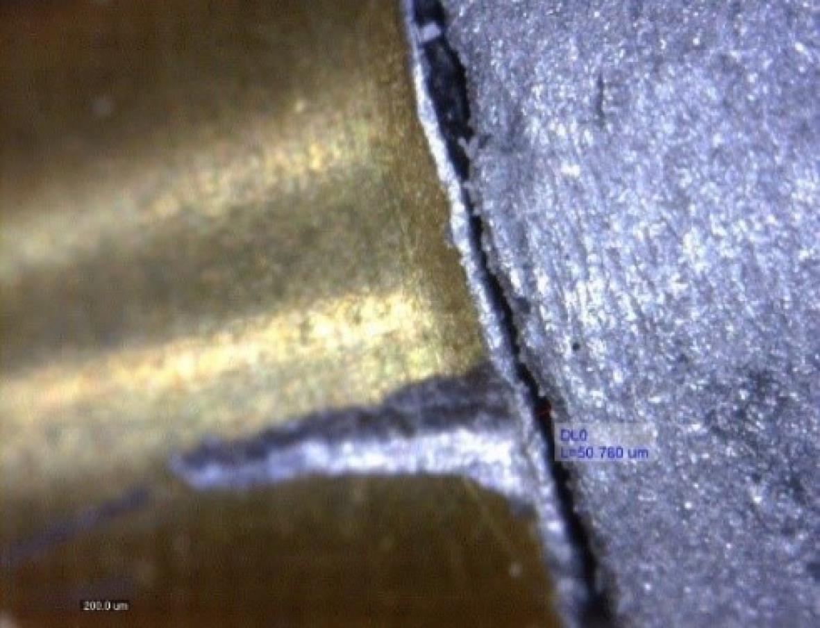
Figure 1.
Image of the Frame Before Porcelain Firing Procedure Obtained With a Stereomicroscope at 204 × Magnification
.
Image of the Frame Before Porcelain Firing Procedure Obtained With a Stereomicroscope at 204 × Magnification
The same steps were followed for the rest of the abutments, and 6 readings were recorded for each framework.
The entire process of adding the veneering porcelain was performed by the same practitioner. The following steps were carried out for all samples: degassing; airborne particle abrasion using 50 μm aluminum oxide particles subjected to 2-bar pressure for 40 seconds at a distance of 10 mm in a sandblasting unit (Basic Classic; Renfert, Hilzingen, Germany), steam-cleaning for 10 minutes to remove the residual aluminum oxide particles, performing two cycles of firing to achieve an opaque porcelain, and one cycle to obtain a fine layer of porcelain on dentin and enamel (Noritake EX-3; Kuraray Noritake Dental Inc., Japan) in a furnace (Vacumat 250; Vita Zahnfabrik, Bad Sackingen, Germany). Finally, following the autoglazing procedure, the same measurements were repeated at the marked points for each sample (Figure 2).
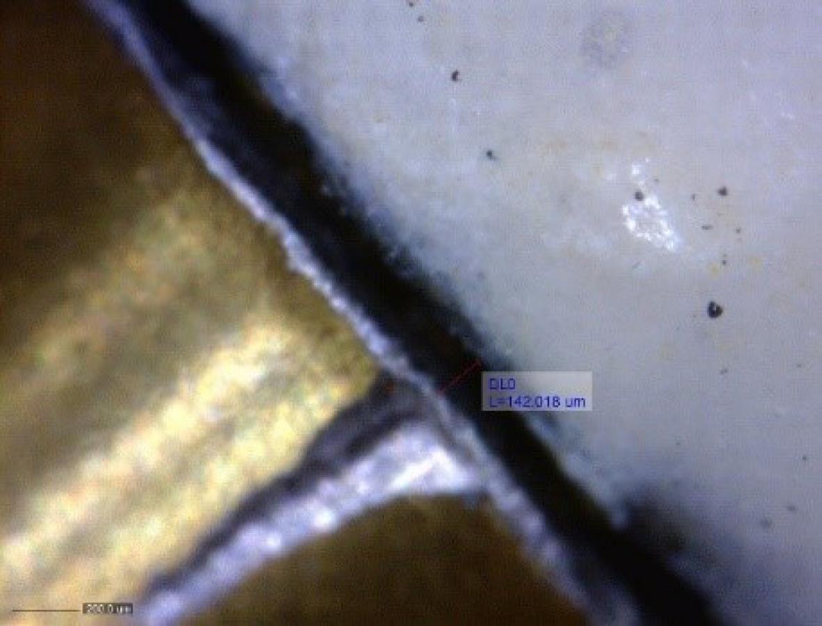
Figure 2.
Image of the Frame After Porcelain Firing Procedure Obtained With a Stereomicroscope at 204 × Magnification
.
Image of the Frame After Porcelain Firing Procedure Obtained With a Stereomicroscope at 204 × Magnification
Data Analysis
The mean values were calculated in micrometer for each group. The Shapiro-Wilk test was used to assess the normality of the data. The data were analyzed using the Kruskal-Wallis test. The Dunn’s post hoc test performed before the veneering procedure and the Tukey’s post hoc test conducted after the veneering procedure were used to compare the mean values where there was a significant difference (α = 0.05).
Results
Mean marginal misfit and standard deviation values of fabrication techniques and veneered/unveneered FDPs are presented in Table 1.
Table 1.
Mean Vertical Misfit Values and Standard Deviation (µm) in Passive Fit Condition for all Groups before and after Porcelain Firing (Veneering)
|
Group
|
Before veneering
|
After veneering
|
|
Mean
|
SD
|
Mean
|
SD
|
| CAD/CAM |
27.90a |
18.48 |
56.74a |
26.29 |
| One-piece casting |
86.47b |
21.36 |
117.34b |
32.39 |
| Soldering |
71.89b |
32.38 |
104.9bc |
36.92 |
| Cast-to |
69.77b |
40.49 |
92.34c |
29.98 |
Values with different lowercase letters indicate statistically significant differences (P < 0.05).
Significant differences were found in passive fit measurements between fabrication techniques before and after veneering (P < 0.001). Frameworks prepared using the CAD/CAM technique showed minimum marginal misfit before the veneering procedure, which was significantly different from other methods (P < 0.05) (Table 2).
Table 2.
Comparison of Fabrication Techniques before Ceramic Veneering Based on Vertical Misfit Values (µm) in Passive Fit Condition
|
Comparison
|
Mean difference (a-b)
|
P
Value
|
| CAD/CAM versus one-piece casting |
-58.57 |
< 0.001* |
| CAD/CAM versus double casting |
-41.87 |
0.001* |
| CAD/CAM versus soldering |
-43.99 |
< 0.001* |
| One-piece casting versus soldering |
14.58 |
0.088 |
| One-piece casting versus double casting |
16.70 |
0.253 |
| Soldering versus double casting |
2.12 |
1 |
*Statistically significant difference; P < 0.05 (Dunn’s test).
After ceramic veneering, the mean marginal misfit values increased significantly in all fabrication methods (P < 0.001). After porcelain firing, the marginal misfit values of the double casting group were significantly lower than those of the one-piece casting group (P = 0.037), but no significant difference was found between one-piece casting and soldering groups (P = 0.527) (Table 3).
Table 3.
Comparison of Fabrication Techniques after Ceramic Veneering Based on Vertical Misfit Values (µm) in Passive Fit Condition
|
Comparison
|
Mean Difference (a-b)
|
P
Value
|
| CAD/CAM versus one-piece casting |
-60.60 |
< 0.001* |
| CAD/CAM versus double casting |
-35.60 |
0.001* |
| CAD/CAM versus soldering |
-48.17 |
< 0.001* |
| One-piece casting versus soldering |
12.43 |
0.527 |
| One-piece casting versus double casting |
25 |
0.037* |
| Soldering versus double casting |
12.57 |
0.517 |
*Statistically significant difference; P < 0.05 (Tukey’s HSD test).
Discussion
Similar to other studies, screw-retained abutments were used in the present study because cement-retained abutments compensate for the interference between the frame and abutment (10). According to the results of this study, the passivity of the fit of screw-retained ISDPs was influenced by the fabrication method. Moreover, CAD/CAM-fabricated ISDPs provided better fit compared to other techniques before the veneering procedure; therefore, the first null hypothesis was rejected.
Marginal misfit of implant-supported prostheses can lead to bacterial invasion into the microgap and subsequent peri-implantitis with progressive bone loss (12). The lack of an accurate fit of a screw-retained superstructure, in addition to the biological complications, may lead to the mechanical failure of the prosthesis as a result of non-passivity and stress concentration on the prosthetic components, especially the prosthetic screw. Therefore, the achievement of an accurate fit plays an important role in the survival of a screw- retained ISDP (13).
The results of this study were consistent with the results of studies conducted by de Araújo et al and de França et al that found higher passivity and lower vertical misfit values for CAD/CAM-fabricated Co-Cr frameworks (FDPs) compared to conventional casting (14,15). Better fit of the CAD/CAM-fabricated frameworks can be attributed to the accuracy and reproducibility of the CAD/CAM procedure and elimination of multiple steps including waxing, investing, wax pattern removal, casting, finishing, and polishing (13). Fernández et al found that the fabrication technique affected the precision of fit because of the differences in the surface roughness. In comparison to casting methods, the superior precision of a milled surface results in more accurate prosthetic connections, which brings the prosthetic components to a very close contact and reduces the microgap (16).
In the present study, the CAD/CAM frameworks were fabricated 10% larger than the expected final size. In this process, the framework was made from soft, non-presintered, Co-Cr blanks to compensate for the amount of alloy shrinkage during the sintering. Therefore, there are concerns regarding the lack of passive fit because of this volumetric shrinkage, which might not occur uniformly in all directions. Vojdani et al found that the marginal fit of the copings produced from hard presintered blanks was significantly better compared to those milled from soft non-presintered blanks; however, both were within a clinically acceptable range (8). Interestingly, the findings of this study demonstrated the effectiveness of soft non-presintered Co-Cr blanks for achieving a high level of passive fit.
According to the results of this study, no significant improvement was observed in passive fit after the soldering procedure compared to one-piece casting. However, das Neves et al found that the soldering procedure resulted in a decrease in acceptable vertical gap values ( < 10 µ) (17). In general, the literature is contradictory regarding the efficacy of the solder approach to improve the passivity of the fit (18). It seems that this approach can only partially compensate for inaccuracies produced by the casting procedure.
Double casting, as an alternative to the solder approach, can reduce the framework distortion during the ceramic firing procedure (2). Nevertheless, the present study found no significant differences in the mean marginal misfit between cast-to and soldered specimens before or after the porcelain firing process.
Similar to a previous study (13), the present study showed that the mean marginal misfit values increased significantly after the porcelain firing procedure in all groups regardless of the fabrication technique. Therefore, the second null hypothesis was also rejected. However, Katsoulis et al found that the porcelain firing procedure had no impact on the passive fit of full arch CAD/CAM titanium frameworks (10). It seems that the framework manufacturing technique, material type, volume of porcelain used, number of firing times, firing temperature, and time as well as the method of marginal gap measurement such as the number of measurement points per specimen can affect the results of different studies.
It should also be noted that different results might be obtained when long-span FDPs are assessed due to the greater volume of porcelain and more effect on framework distortion.
DeHoff et al evaluated the effectiveness of cast-joint Ni-Cr structure under flexural loading. They concluded that the risk of joint fracture might increase in the presence of a high level of flexural stress (19). However, this study used a modified cast-to method in which the second casting completely encases the first to eliminate the potential weak joint.
Studies conducted in this field have used several methods (strain gauge, electronic and optical microscope, virtually coordinated measuring machine, etc.) to evaluate the marginal gap. However, Katsoulis et al (10) and de Araújo et al (14) found that the best methods for assessing the marginal gap were optical and electron microscopes. Optical microscopy was used in the present study.
In order to standardize future studies, it is better to test the marginal fit using two methods, including tightening one screw (passive fit) and all screws (final fit). The present study used the one-screw test according to a previous study (14).
Limitations of the Study
There were some limitations in this study as well. In vivo studies should also be performed for the validation of the results. Frames and porcelain veneering should be fabricated with more accurate methods. This study can be a basis for finding more accurate methods of fabricating frames.
Conclusions
Considering the limitations of this study, the following conclusions were made. The passivity of fit of screw-retained FDPs was influenced by the manufacturing technique. Soft non-presintered CAD/CAM frameworks exhibited better passivity compared to three conventional methods. The ceramic firing procedure resulted in lower passivity of fit of screw-retained FDPs in all fabrication methods. After ceramic firing, there was no significant difference between the samples in terms of accuracy and component passivity.
Acknowledgments
The authors would like to thank the Dental Research Center of Mashhad Dental School. The results presented here are based on the results of an undergraduate thesis (No.2878) submitted to Mashhad School of Dentistry and Dental Research Center.
Authors’ Contribution
The present study was planned by Mohamad Reza Nakhaee and Azizollah Moraditalab. The statistical analyses and interpretation of data were carried out by Mohamad Reza Nakhaee, Atefe Mottaghianfar, and Davood Nodehi. Davood Nodehi wrote the original draft of the article. All the authors have read and approved the final manuscript.
Competing Interests
There is no conflict of interests.
Funding
This study was supported by a grant (941522) from the Research Council of Mashhad University of Medical Sciences.
References
- Abduo J, Lyons K, Bennani V, Waddell N, Swain M. Fit of screw-retained fixed implant frameworks fabricated by different methods: a systematic review. Int J Prosthodont 2011; 24(3):207-20. [ Google Scholar]
- Abduo J, Lyons K, Swain M. Fit of zirconia fixed partial denture: a systematic review. J Oral Rehabil 2010; 37(11):866-76. doi: 10.1111/j.1365-2842.2010.02113.x [Crossref] [ Google Scholar]
- Anusavice KJ, Okabe T, Galloway SE, Hoyt DJ, Morse PK. Flexure test evaluation of presoldered base metal alloys. J Prosthet Dent 1985; 54(4):507-17. doi: 10.1016/0022-3913(85)90423-8 [Crossref] [ Google Scholar]
- Luk HW, Pow EH, McMillan AS, Hui CF. A double casting technique to minimize distortion when constructing fixed partial dentures on implants. J Prosthet Dent 2004; 91(1):93-6. doi: 10.1016/j.prosdent.2003.09.013 [Crossref] [ Google Scholar]
- Karl M, Graef F, Wichmann M, Krafft T. Passivity of fit of CAD/CAM and copy-milled frameworks, veneered frameworks, and anatomically contoured, zirconia ceramic, implant-supported fixed prostheses. J Prosthet Dent 2012; 107(4):232-8. doi: 10.1016/s0022-3913(12)60067-5 [Crossref] [ Google Scholar]
- Abou Tara M, Eschbach S, Bohlsen F, Kern M. Clinical outcome of metal-ceramic crowns fabricated with laser-sintering technology. Int J Prosthodont 2011; 24(1):46-8. [ Google Scholar]
- Örtorp A, Jönsson D, Mouhsen A, Vult von Steyern P. The fit of cobalt-chromium three-unit fixed dental prostheses fabricated with four different techniques: a comparative in vitro study. Dent Mater 2011; 27(4):356-63. doi: 10.1016/j.dental.2010.11.015 [Crossref] [ Google Scholar]
- Vojdani M, Torabi K, Atashkar B, Heidari H, Torabi Ardakani M. A comparison of the marginal and internal fit of cobalt- chromium copings fabricated by two different CAD/CAM systems (CAD/milling, CAD/Ceramill Sintron). J Dent (Shiraz) 2016; 17(4):301-8. [ Google Scholar]
- Cuiling L, Liyuan Y, Xu G, Hong S. [Influence of coping material selection and porcelain firing on marginal and internal fit of computer-aided design/computer- aided manufacturing of zirconia and titanium ceramic implant-supported crowns]. Hua Xi Kou Qiang Yi Xue Za Zhi 2016; 34(3):262-6. doi: 10.7518/hxkq.2016.03.009.[Chinese] [Crossref] [ Google Scholar]
- Katsoulis J, Mericske-Stern R, Enkling N, Katsoulis K, Blatz MB. In vitro precision of fit of computer-aided designed and computer-aided manufactured titanium screw-retained fixed dental prostheses before and after ceramic veneering. Clin Oral Implants Res 2015; 26(1):44-9. doi: 10.1111/clr.12299 [Crossref] [ Google Scholar]
- Tiossi R, Falcão-Filho H, Aguiar Júnior FA, Rodrigues RC, da Gloria Chiarello de Mattos, Ribeiro RF. Modified section method for laser-welding of ill-fitting cp Ti and Ni-Cr alloy one-piece cast implant-supported frameworks. J Oral Rehabil 2010; 37(5):359-63. doi: 10.1111/j.1365-2842.2010.02063.x [Crossref] [ Google Scholar]
- Teixeira W, Ribeiro RF, Sato S, Pedrazzi V. Microleakage into and from two-stage implants: an in vitro comparative study. Int J Oral Maxillofac Implants 2011; 26(1):56-62. [ Google Scholar]
- Patil A, Singh K, Sahoo S, Suvarna S, Kumar P, Singh A. Comparative assessment of marginal accuracy of grade II titanium and Ni-Cr alloy before and after ceramic firing: an in vitro study. Eur J Dent 2013; 7(3):272-7. doi: 10.4103/1305-7456.115409 [Crossref] [ Google Scholar]
- de Araújo GM, de França DG, Silva Neto JP, Barbosa GA. Passivity of conventional and CAD/CAM fabricated implant frameworks. Braz Dent J 2015; 26(3):277-83. doi: 10.1590/0103-6440201300145 [Crossref] [ Google Scholar]
- de França DG, Morais MH, das Neves FD, Carreiro AF, Barbosa GA. Precision fit of screw-retained implant-supported fixed dental prostheses fabricated by CAD/CAM, copy-milling, and conventional methods. Int J Oral Maxillofac Implants 2017; 32(3):507-13. doi: 10.11607/jomi.5023 [Crossref] [ Google Scholar]
- Fernández M, Delgado L, Molmeneu M, García D, Rodríguez D. Analysis of the misfit of dental implant-supported prostheses made with three manufacturing processes. J Prosthet Dent 2014; 111(2):116-23. doi: 10.1016/j.prosdent.2013.09.006 [Crossref] [ Google Scholar]
- das Neves FD, Elias GA, da Silva-Neto JP, de Medeiros Dantas LC, da Mota AS, Neto AJ. Comparison of implant-abutment interface misfits after casting and soldering procedures. J Oral Implantol 2014; 40(2):129-35. doi: 10.1563/aaid-joi-d-11-00070 [Crossref] [ Google Scholar]
- Watanabe F, Uno I, Hata Y, Neuendorff G, Kirsch A. Analysis of stress distribution in a screw-retained implant prosthesis. Int J Oral Maxillofac Implants 2000; 15(2):209-18. [ Google Scholar]
- DeHoff PH, Anusavice KJ, Evans J, Wilson HR. Effectiveness of cast-joined Ni-Cr-Be structures. Int J Prosthodont 1990; 3(6):550-4. [ Google Scholar]